|
Notice: This page contains information for the legacy Phidget21 Library. Phidget21 is out of support. Bugfixes may be considered on a case by case basis. Phidget21 does not support VINT Phidgets, or new USB Phidgets released after 2020. We maintain a selection of legacy devices for sale that are supported in Phidget21. We recommend that new projects be developed against the Phidget22 Library.
|
Strain Gauge Primer
Introduction

Strain gauges are devices used to measure strain on an object. They are attached to an object and as the object deforms under strain the gauge will deform with it. Strain gauges are designed to change resistance when they deform and by measuring this change in resistance strain gauges can be used to detect how much stress is being placed on the object. The most common way to measure the resistance change is through the use of a Wheatstone bridge such as the 1046. Strain gauges are most often encountered not individually, but in pairs or quartets as part of a load cell.
Getting Started
Strain gauges by themselves are great for making your own load cells. DIY load cells like this are useful for when conventional load cells are impractical to install. When you want to install strain gauges in your system to measure force the first step is to select the part of your system you want to convert into the load cell. This is typically referred to as the spring element. There are a few things you need to consider when selecting what part of your system you want to use at the spring element:
- What material is the spring element made of? Steel and aluminium are the two recommended materials and they each require a different type of strain gauge for effective use.
- For optimal performance we recommend 4140, 4340 and 17-4PH steel as well as 2024-T8 aluminium. Other types of steel and aluminium will work, these are just the most responsive types.
- Despite the name, the spring element should be chosen for minimal compliance i.e. minimal displacement under rated load. The spring element should appear to be completely rigid under full load, the strain gauge is capable of measuring imperceptible deflection in the spring element and anything more has a good chance of causing damage to the spring element which would permanently damage the load cell.
Before going further, there is one thing that is important to remember: When this document refers to a strain gauge it means a single, 2 wire, gauge. All of what Phidgets sells are either half bridges, or full bridges. This means they are a collection of 2 or 4 individual strain gauges hooked up in a useful pattern. That said, you can always isolate a single gauge from the half bridge or full bridge by simply leaving some of the channels on the unit not connected. For example, a half bridge will have 3 wires, one for either end of the 2 gauge pair and one for the middle, where the two gauges connect. If you want to only use one of the gauges then you can simply connect leads to one of the end terminals and to the central terminal.
Choosing a Strain Gauge Configuration
Depending on what you want to measure there are different ways you can configure your strain gauges to measure different forces. For example to measure radial force (bending) you would mount and connect your strain gauges differently than if you wanted to measure axial force (compression or tension), torque, or even gas pressure in a pipe. Lets quickly go through the different configurations that you can use to measure different forces.
Radial Force
Measurements of radial force are done with a cantilever type spring element. For example, consider a straight metal beam protruding from a wall:
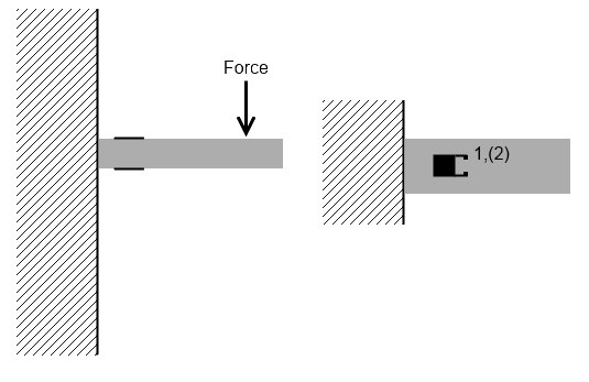
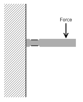
This set up is known as a bending beam transducer. It is important that the strain gauges be applied along the centre line of the spring element and they both the strain gauges on top and bottom be placed an equal distance from the fixed point (in the image, the wall). The gauges should be installed fairly close to the fixed point in relation to the length of the beam. The cantilever beam as shown above is somple to design and fabricate and makes installing strain gauges fairly easy. It is also fairly immune to loads applied in axes other than the intended measurement axis. The main problem with the cantilever style is that beam can bend and cause distorted readings. One solution is to make the beam thinner around the strain gauges. This will focus the strain to this specific region of the beam and minimize bending in the rest of the system. For example:
Once the strain gauges are in place you need to connect them to the 1046. You will want to connect them in the following pattern:
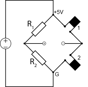
Where R1 and R2 are two resistors of the same resistance. We recommend the 3175 resistors since their resistance value is the same to a high precision. +5V, +, -, and G are the 4 terminals of the PhidgetBridge. And 1 and 2 are the strain gauges as labelled on the drawings above. For this configuration you will want to use individual strain gauges. You can use a half bridge on top and bottom and only connect one of the gauges to achieve this.
Axial Compression/Tension
To measure axial force (either tension or compression) a column load cell is used.

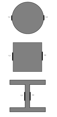
The image shown is a cylindrical spring element, this is one possible cross section but others are also acceptable. The important part is that the load is applied along the axis of the spring element. The strain gauges must also be at the same position on the spring element and diametrically opposed. The strain gauges are then connected to the 1046 as follows:
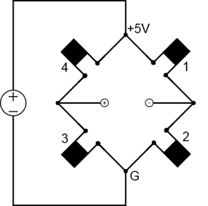
Due to the way the strain gauges are configured in this bridge all bending force will be cancelled out and only the axial force will be measured. This is desirable but it does mean that the force should be applied in parallel with the axis of the spring element. Any component of the force that is not parallel to the axis will be cancelled out of the measurement. The perpendicular strain gauges will also allow for thermal effects to be cancelled as well. You will need a full 4 strain gauges for this set up. 2 half bridges would be suitable.
Torque

Although less common than radial force or compression/tension, torque is an important mechanical force that can be measured with custom load cells and strain gauges. Measuring torque with strain gauges is really only appropriate for bar like spring elements such as in the column load cells described previously. The difficult part about torque is that the strain gauges have to be installed 45° with respect to the central axis of the spring element. This makes it quite difficult to properly align the strain gauges, especially when the surface of the spring elemental is curved as in the case of a round pipe or bar stock. To mitigate this difficulty we have strain gauges that are at 45° angles already. They should be installed as shown in the following diagram:
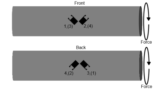
Making sure the gauges are installed with their center exactly on the spring elements center line is important. The strain gauges connect to the 1046 in a full bridge pattern as follows:
Installing Strain Gauges

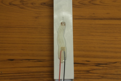
Once you have decided generally where you want the strain gauges to be mounted it is time to attach them to the surface of the spring element. This is the part where patience and precision pay off, as the more accurately you can line up the strain gauges, the more accurate your measurements are going to be. For this guide, I will walk through all the steps required to install a strain gauge on a bare piece of scrap aluminium we had kicking around the office.
The first step is to use some sand paper or steel wool to rough up the surface of the spring element. Since we are going to be using glue to hold the strain gauge in place, we want to ensure the best adhesion possible. Not only does sanding the metal a bit remove any foreign material from the surface, it also increases the surface area exposed to give the glue more to grab on to. Once you have done this make sure to clean the area well. Any powder left behind needs to be removed before we move forward. I recommend using a bit of rubbing alcohol since it will evaporate quickly and not leave any residue behind that might interfere with the glue curing process.
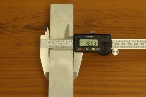
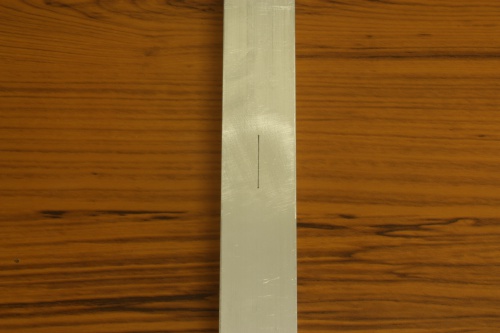
We need to mount the strain gauge as close to the center of the spring element as we can manage. Measure the width of the spring element with the most accurate tool available to you. When gluing the strain gauge to the surface of the spring element, line it up as best as you can with the mark you made previously. In this case I have split the half bridge gauge I am using horizontally. Depending on your set up you may want to split it vertically over the line or only line up a single gauge (quarter bridge) on the line etc... Make sure you know exactly how the gauge needs to be lined up before you stick it on. The super glue is not going to give you a lot of play once you apply the gauge.
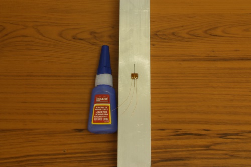
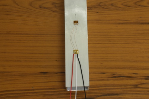
Now that the strain gauge is mounted, we need to attach the terminal tab which we will be using to connect leads to the strain gauge. It should have an adhesive backing, just remove the sticker paper and attach it to the spring element making sure that it is close enough that the wires on the strain gauge can all reach it. Wait a few minutes to ensure the glue on the strain gauge has dried completely, then solder the wires onto the terminal tab. The leads are coated in a resin to prevent them from conducting so you don't need to worry about them contacting the metal spring element or each other. Only the tips of the wires are stripped bare and suitable for conducting. On the other half of the terminal tab you can solder on some wires to connect to the 1046.
Finally, we will want to protect the strain gauge some how. Covering the whole assembly in some kind of protective coating is common practice in commercial load cells. I used epoxy resin in this case but silicone would also work. Just make sure that whatever you do end up using isn't conductive!