|
Notice: This page contains information for the legacy Phidget21 Library. Phidget21 is out of support. Bugfixes may be considered on a case by case basis. Phidget21 does not support VINT Phidgets, or new USB Phidgets released after 2020. We maintain a selection of legacy devices for sale that are supported in Phidget21. We recommend that new projects be developed against the Phidget22 Library.
|
Access Control: Difference between revisions
| Line 28: | Line 28: | ||
#Use your fish tape to feed the USB cable through the hole and then fish it through the electrical box. | #Use your fish tape to feed the USB cable through the hole and then fish it through the electrical box. | ||
#Insert the box into the hole you created and screw it in place. | #Insert the box into the hole you created and screw it in place. | ||
#Use the exterior caulk to create a seal between the box and the wall. | |||
#The easiest thing to do now is to fasten the RFID reader to the faceplate via glue or foam tape. | #The easiest thing to do now is to fasten the RFID reader to the faceplate via glue or foam tape. | ||
#Attach the faceplate to the electrical box and this part is finished. | #Attach the faceplate to the electrical box and this part is finished. | ||
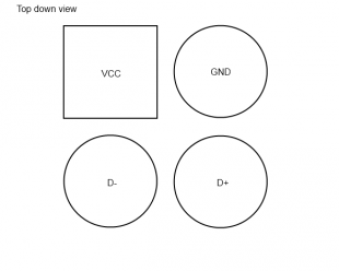
[[image:rfidusbpinout.png|thumb|310px|link=|Pinout of the RFID USB header as viewed from the top down (as if looking through the board).]] | [[image:rfidusbpinout.png|thumb|310px|link=|Pinout of the RFID USB header as viewed from the top down (as if looking through the board).]] | ||
If you find you are having trouble getting the USB plug to fit in the box you can always remove the plug and solder the wires directly to the pins on the underside of the RFID reader. | If you find you are having trouble getting the USB plug to fit in the box you can always remove the plug and solder the wires directly to the pins on the underside of the RFID reader. Depending on where you install the box it may also be a good idea to use some foam weather stripping to enhance the seal of the faceplate to the box. | ||
On the inside you will need to mount the SBC. | On the inside you will need to mount the SBC. | ||
Next we need to have a method for actually unlocking the door. For this project we will be using an electric strike. An electric strike is a device that replaces the hardware on the jamb of the door. Electric strikes can be difficult to install, usually they are used in metal frame doors since the jambs tend to be hollow in these cases which makes running wires much easier. However, there are strikes made specifically for wooden doors. In general, you should follow the instructions that come with the strike for installation. | |||
{| | {| | ||
|[[image:metaldoorjamb.jpg|thumb|left|500px|link=http://sl/wiki/images/3/3d/Metaldoorjamb.jpg|Metal door jamb with precut whole for a strike plate. Note that since the frame is hollow wiring can be run through it fairly easily.]]||[[image:wooddoorjamb.jpg|thumb|left|500px|link=http://sl/wiki/images/a/af/Wooddoorjamb.jpg|Wood door jamb with traditional strike plate installed. This needs to be removed, and a large | |[[image:metaldoorjamb.jpg|thumb|left|500px|link=http://sl/wiki/images/3/3d/Metaldoorjamb.jpg|Metal door jamb with precut whole for a strike plate. Note that since the frame is hollow wiring can be run through it fairly easily.]]||[[image:wooddoorjamb.jpg|thumb|left|500px|link=http://sl/wiki/images/a/af/Wooddoorjamb.jpg|Wood door jamb with traditional strike plate installed. This needs to be removed, and a large hole cut out for the electric strike.]] | ||
|} | |} | ||
While installing the strike keep in mind what you are going to need to do with the wires. You need to run wires from the power supply to the strike and from the relay to the strike. | |||
The layout for the setup is as follows: | The layout for the setup is as follows: | ||
Revision as of 16:49, 30 March 2012
This project will help you set up a keyless entry system for any door in your house, specifically we want to create a system that will unlock a door when a recognized RFID tag is detected. Keyless entry systems have been in use in large facilities for years so why not your house too? At the flash of a card or key-chain your door will automatically unlock, no need to fumble around with a set of keys to find the right key which inevitably takes a few tries.
| Hardware Difficulty: | image here | Software Difficulty: | image here | Time Commitment: | image here | Awesome: | image here |
This project includes:
- Some tricky wiring
- Protecting your devices against the elements
| Phidgets | Parts | Tools |
| 1 1023_1 - PhidgetRFID 1 1072_0 - PhidgetSBC2 |
1 Double gang electrical box 1 Faceplate for the box |
Drill with a large bore drill bit Fish tape A selection of screwdrivers Exterior Caulk |
Warning: Before you begin this project take note: We will be drilling holes in an exterior wall, make sure to check with local building codes to ensure the modifications you are making are legal.
Setting it up
The most difficult part with this project is installing all the components. We are trying to mount hardware on both the exterior and interior of the wall, this can be tricky as cables will need to be run through the wall. Since exterior walls have insulation in them, feeding wires through can be difficult.
- The first step is to cut a hole in the exterior wall that is large enough to fit the box you have gotten.
- You will need to drill a hole through the interior side of the wall inline with this large hole.
- Use your fish tape to feed the USB cable through the hole and then fish it through the electrical box.
- Insert the box into the hole you created and screw it in place.
- Use the exterior caulk to create a seal between the box and the wall.
- The easiest thing to do now is to fasten the RFID reader to the faceplate via glue or foam tape.
- Attach the faceplate to the electrical box and this part is finished.
If you find you are having trouble getting the USB plug to fit in the box you can always remove the plug and solder the wires directly to the pins on the underside of the RFID reader. Depending on where you install the box it may also be a good idea to use some foam weather stripping to enhance the seal of the faceplate to the box.
On the inside you will need to mount the SBC.
Next we need to have a method for actually unlocking the door. For this project we will be using an electric strike. An electric strike is a device that replaces the hardware on the jamb of the door. Electric strikes can be difficult to install, usually they are used in metal frame doors since the jambs tend to be hollow in these cases which makes running wires much easier. However, there are strikes made specifically for wooden doors. In general, you should follow the instructions that come with the strike for installation.


While installing the strike keep in mind what you are going to need to do with the wires. You need to run wires from the power supply to the strike and from the relay to the strike.
The layout for the setup is as follows:

Software
We want the program to have the following structure:

There are several cases for the software for this project. They are as follows:
| Case | Access Method | Unlock Method |
| 1 | RFID | Electric Strike |
| 2 | RFID | Motorized Deadbolt |
| 3 | Keypad | Electric Strike |
| 4 | Keypad | Motorized Deadbolt |
For case 1, we need to have code that checks RFID tag events against a list or database of accepted tags and if the tag is a recognized tag, switch power on to the electric strike.
rfid.addTagGainListener(new TagGainListener()
{
	public void tagGained(TagGainEvent oe)
	{
		String line = null;
		try{
			reader = new Scanner(inFile); // set the scanner to read in from the appropriate file
		}
		catch(Exception e){}
		while(reader.hasNextLine()){  // read through the entire file
			try{
				line = reader.nextLine(); //read in the current tag data
				if(line.equals(oe.toString())){ //does the active tag match this entry?
					ik.setOutputState(0,true); //if so activate the relay.
				}
			}
			catch(Exception e){}
		}
		reader.close();
	}
});
Where inFile is a File object set to the file in which the tag data is stored. The data can be read into a file off line prior to installing, or at will with the push of a button or the swipe of a master tag etc... depending on what you prefer. You can download the full file here. Note that this code has a mechanism for reading tags into a file though in practice you would want this system to be a bit more robust. Perhaps by using a database of some kind. This way you could also log who specifically was accessing the door etc...
In case 2, the code will look almost the same except instead of
ik.setOutputState(0,true);
We need to set the motor to the correct position for the unlocked state:
servo.setPosition(0, DOORUNLOCKED);
The door's locked and unlocked positions can be determined experimentally once the assembly has been installed. The full code can be downloaded here. In this code the settings for DOORLOCKED and DOORUNLOCKED are arbitrary and will not have much bearing on the finished product.
Case 3 involves a number sequence detection algorithm. The length of the input sequence is arbitrary. The interface kit input change handler should look something like this:
ik.addInputChangeListener(new InputChangeListener() {
	public void inputChanged(InputChangeEvent oe) {
		if(oe.getState() == false) //we want to ignore the changes that occur from depressing a button
			return;

		keyCode = keyCode + oe.getIndex(); //append new entry to current attempt
		index++; //increment place marker

		if(keyCode.equals(UNLOCK)){ //if the attempt = the accepted answer
			try{
				ik.setOutputState(0,true); //unlock
				Thread.sleep(2000); //pause for opening
				ik.setOutputState(0,false); //relock
				keyCode = ""; //reset the current attempt to blank
			}
			catch(Exception e){}
		}
		if(index ==4){ //if the current attempt has reached the 4 digit limit, reset.
			index = 0;
			keyCode = "";
		}
	}
});
Where UNLOCK is whatever (in this case 4 digit long) sequence of numbers you choose. The rest of the file is available here.
Case 4 is almost exactly the same as 3, except that once again we must replace the ik.setOutputState line with code that moves the motor. Refer to case 2 for more on this.