|
Notice: This page contains information for the legacy Phidget21 Library. Phidget21 is out of support. Bugfixes may be considered on a case by case basis. Phidget21 does not support VINT Phidgets, or new USB Phidgets released after 2020. We maintain a selection of legacy devices for sale that are supported in Phidget21. We recommend that new projects be developed against the Phidget22 Library.
|
Access Control: Difference between revisions
No edit summary |
No edit summary |
||
| (46 intermediate revisions by 5 users not shown) | |||
| Line 4: | Line 4: | ||
[[Category: mounting]] | [[Category: mounting]] | ||
[[Category: PhidgetsSBC]] | [[Category: PhidgetsSBC]] | ||
This project will help you set up a keyless entry system for any door in your house, specifically we want to create a system that will unlock a door when a recognized RFID tag is detected. | [[Category: Application Guides]] | ||
This project will help you set up a keyless entry system for any door in your house, specifically we want to create a system that will unlock a door when a recognized RFID tag is detected. | |||
{| | {| | ||
| | |Practical concepts covered are (click on links to see other projects on that topic): | ||
* [[:Category:cabling|Cabling]] | |||
* [[:Category:Weatherproofing|Weatherproofing]] | |||
* [[:Category:mounting|Hardware Mounting]] | |||
* [[:Category:PhidgetSBC|Using the Phidget SBC]] | |||
|width="45px"| | |||
|[[File:doorunlockfull.png|500px|link=|alt=]] | |||
|} | |} | ||
{| style="border:1px solid darkgray;" cellpadding="5px;" | |||
|'''Time:''' | |||
| About a full day of work, including gathering components, writing code, and drilling/assembling.<br> The challenge will be mounting, wiring, weather proofing, and running power to your system - the code is relatively easy. | |||
|- | |||
{|border | |'''Special Needed Tools:''' | ||
|A selection of screwdrivers, Drill with a large bore drill bit, Fish tape, Exterior Caulk | |||
|- | |||
|'''Phidgets Needed:''' | |||
|A [{{SERVER}}/products.php?product_id=1024 1024 - PhidgetRFID Read/Write], a [{{SERVER}}/products.php?product_id=1072 1072 - PhidgetSBC2] or [{{SERVER}}/products.php?product_id=1073 1073 - PhidgetSBC3], and a [{{SERVER}}/products.php?product_id=3052 3052 - SSR Relay Board] | |||
|- | |- | ||
| | |'''Materials Needed:''' | ||
| A Double gang electrical box, and faceplate for the box | |||
|} | |} | ||
As with any of our [[:Category:Application Guides|described projects]], Phidgets takes care of the electrical component design. Here, we walk you through the code and hardware connections to create a system out of our ready made boards. | |||
'''''Warning: '''''Before you begin this project note that we will be '''drilling holes in an exterior wall''', so make sure to check with local building codes to ensure the modifications you are making are legal. | |||
==Introduction== | |||
Keyless entry systems have been in use in large facilities for years so why not your house too? At the flash of a card or key-chain your door will automatically unlock, no need to fumble around in the dark with a set of keys to find the right key which inevitably takes a few tries. | |||
==Setting it up== | |||
The most difficult part with this project is installing all the components. We are trying to mount hardware on both the exterior and interior of the wall; this can be tricky as cables will need to be run through the wall. Since exterior walls have insulation in them, feeding wires through can be difficult. | |||
#The first step is to cut a hole in the exterior wall that is large enough to fit the box you have gotten. | |||
#You will need to drill a hole through the interior side of the wall inline with this large hole. | |||
#Use your fish tape to feed the USB cable through the hole and then fish it through the electrical box. | |||
#Insert the box into the hole you created and screw it in place. | |||
#Use the exterior caulk to create a seal between the box and the wall. | |||
#The easiest thing to do now is to fasten the RFID reader to the faceplate via glue or foam tape. | |||
#Attach the faceplate to the electrical box and this part is finished. | |||
Depending on where you install the box it may also be a good idea to use some foam weather stripping to enhance the seal of the faceplate to the box. | |||
On the inside you will need to mount the SBC. This can be done many ways though the obvious choice is to do the same thing as you did for the RFID reader. Since the location of the SBC is less important you could even put it down at foot level, out of sight. Alternatively you could mount it in an enclosure directly on the wall. If you have a basement or crawlspace underneath your front door you could also mount it on the rafters below the door. Having the SBC be connected to the internet will help debug issues, keep maintenance easy, and allow for easier addition of new tags | |||
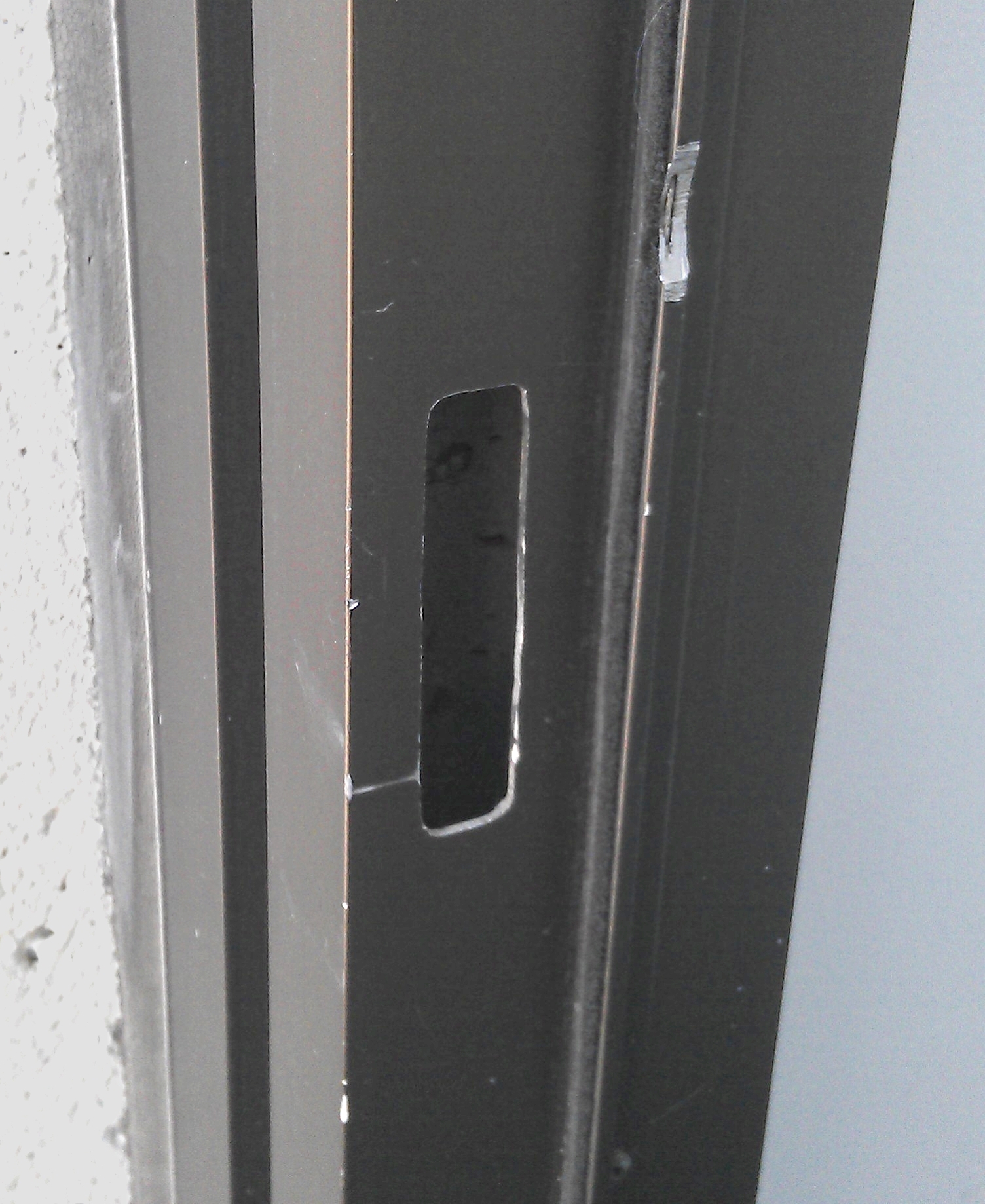
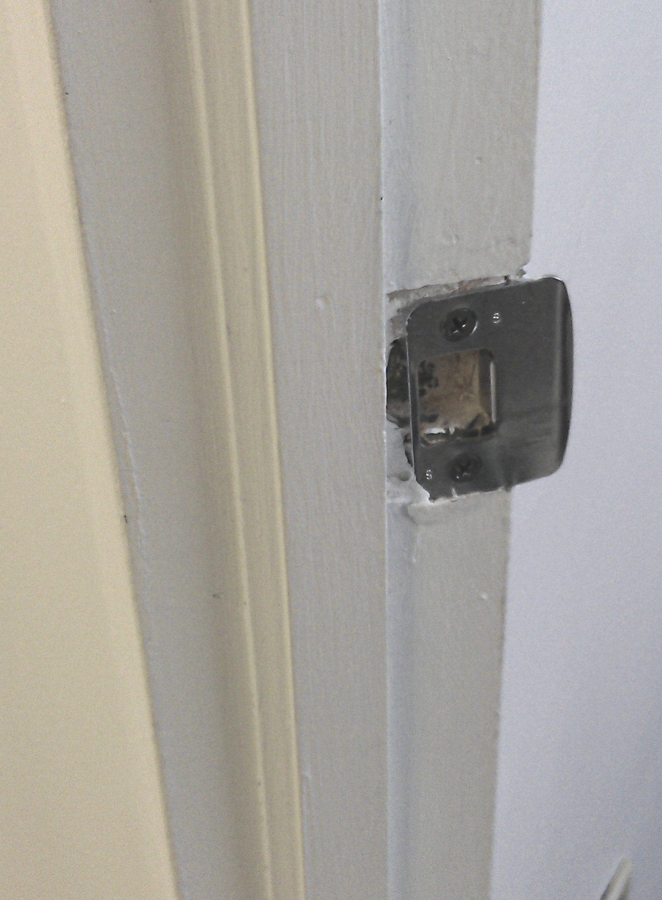
Next we need to have a method for actually unlocking the door. For this project we will be using an electric strike. An electric strike is a device that replaces the hardware on the jamb of the door. Electric strikes can be difficult to install, usually they are used in metal frame doors since the jambs tend to be hollow in these cases which makes running wires much easier. However, there are strikes made specifically for wooden doors. In general, you should follow the instructions that come with the strike for installation. | |||
{| | {| | ||
|[[ | |[[File:metaldoorjamb.jpg|thumb|left|310px|link={{SERVER}}/docs21/images/3/3d/Metaldoorjamb.jpg|Metal door jamb with precut hole for a strike plate. Note that since the frame is hollow wiring can be run through it fairly easily.]]||[[File:wooddoorjamb.jpg|thumb|right|310px|link={{SERVER}}/docs21/images/a/af/Wooddoorjamb.jpg|Wood door jamb with traditional strike plate installed. This needs to be removed, and a large hole cut out for the electric strike.]] | ||
|} | |} | ||
While installing the strike keep in mind what you are going to need to do with the wires. You need to run wires from the power supply to the relay and from the relay to the strike. | |||
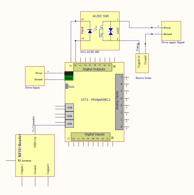
This is the functional schematic for the components of this project:<br /> | |||
[[File:doorlockblockdiagram.png|600px|link={{SERVER}}/docs21/images/5/54/Doorlockblockdiagram.png]]<br /> | |||
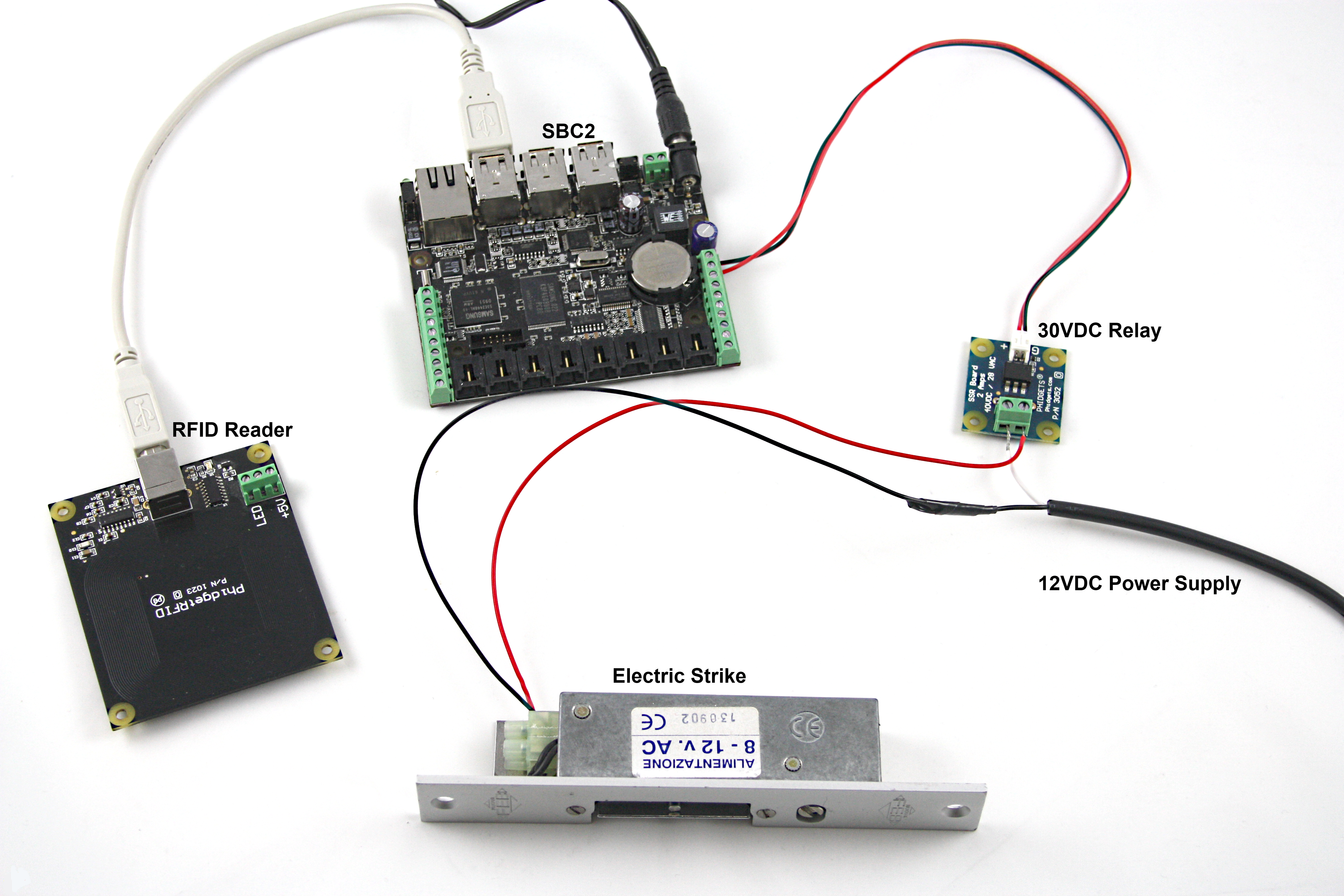
This is how it would look in real life<br /> | |||
[[File:doorunlockfull.png|600px|link={{SERVER}}/docs21/images/a/aa/Doorunlockfull.png]] | |||
==Software== | |||
We want the program to have the following process flow: | |||
[[File:Gliffyflowchart.png|link=|alt=|900px]] | |||
[[ | |||
| | |||
We need to have code that checks RFID tag events against a list or database of accepted tags and if the tag is a recognized tag, switch power on to the electric strike. | |||
<div class="source"> | <div class="source"> | ||
| Line 107: | Line 95: | ||
</div> | </div> | ||
Where ''inFile'' is a File object set to the file in which the tag data is stored. The | Where ''inFile'' is a File object set to the file in which the tag data is stored. The tags can be read into a file off-line prior to normal operation, or at will with the push of a button depending on what you prefer. You can download the full code [{{SERVER}}/docs21/images/c/c9/DoorUnlocker.java here]. Note that this code has a mechanism for reading tags into a file though it is for demonstration purposes. In practice you would want the tag reading system to be a bit more robust. Perhaps by using a database of some kind so you could also log who specifically was accessing the door etc... | ||
When the tag is no longer detected the door should relock, though we want to have a window in which the user can still open the door before it locks. This can be handled in our tag loss handler: | |||
<div class="source"> | <div class="source"> | ||
<syntaxhighlight lang=java> | <syntaxhighlight lang=java> | ||
ik.setOutputState(0, | delay = new javax.swing.Timer(SHORTDELAY, new ActionListener(){ //SHORTDELAY is an arbitrary number of milliseconds | ||
public void actionPerformed(ActionEvent evt){ | |||
try{ | |||
ik.setOutputState(0,false); | |||
} | |||
catch(Exception e){} | |||
delay.stop(); | |||
} | |||
}); | |||
rfid.addTagLossListener(new TagLossListener() | |||
{ | |||
public void tagLost(TagLossEvent oe) | |||
{ | |||
try{ | |||
if(ik.getOutputState(0) == true){ | |||
delay.start(); //add a short delay so the user has time to open the door | |||
} | |||
} | |||
catch(Exception e){} | |||
} | |||
}); | |||
</syntaxhighlight> | </syntaxhighlight> | ||
</div> | </div> | ||
<!-- | |||
'''Case 3''' involves a number sequence detection algorithm. The length of the input sequence is arbitrary. The interface kit input change handler should look something like this: | '''Case 3''' involves a number sequence detection algorithm. The length of the input sequence is arbitrary. The interface kit input change handler should look something like this: | ||
| Line 156: | Line 159: | ||
</div> | </div> | ||
Where ''UNLOCK'' is whatever (in this case 4 digit long) sequence of numbers you choose. The rest of the file is available [ | Where ''UNLOCK'' is whatever (in this case 4 digit long) sequence of numbers you choose. The rest of the file is available [{{SERVER}}/docs21/images/4/43/KeypadUnlocker.java here]. | ||
--> | |||
Latest revision as of 18:35, 7 June 2017
This project will help you set up a keyless entry system for any door in your house, specifically we want to create a system that will unlock a door when a recognized RFID tag is detected.
| Practical concepts covered are (click on links to see other projects on that topic): | 
|
| Time: | About a full day of work, including gathering components, writing code, and drilling/assembling. The challenge will be mounting, wiring, weather proofing, and running power to your system - the code is relatively easy. |
| Special Needed Tools: | A selection of screwdrivers, Drill with a large bore drill bit, Fish tape, Exterior Caulk |
| Phidgets Needed: | A 1024 - PhidgetRFID Read/Write, a 1072 - PhidgetSBC2 or 1073 - PhidgetSBC3, and a 3052 - SSR Relay Board |
| Materials Needed: | A Double gang electrical box, and faceplate for the box |
As with any of our described projects, Phidgets takes care of the electrical component design. Here, we walk you through the code and hardware connections to create a system out of our ready made boards.
Warning: Before you begin this project note that we will be drilling holes in an exterior wall, so make sure to check with local building codes to ensure the modifications you are making are legal.
Introduction
Keyless entry systems have been in use in large facilities for years so why not your house too? At the flash of a card or key-chain your door will automatically unlock, no need to fumble around in the dark with a set of keys to find the right key which inevitably takes a few tries.
Setting it up
The most difficult part with this project is installing all the components. We are trying to mount hardware on both the exterior and interior of the wall; this can be tricky as cables will need to be run through the wall. Since exterior walls have insulation in them, feeding wires through can be difficult.
- The first step is to cut a hole in the exterior wall that is large enough to fit the box you have gotten.
- You will need to drill a hole through the interior side of the wall inline with this large hole.
- Use your fish tape to feed the USB cable through the hole and then fish it through the electrical box.
- Insert the box into the hole you created and screw it in place.
- Use the exterior caulk to create a seal between the box and the wall.
- The easiest thing to do now is to fasten the RFID reader to the faceplate via glue or foam tape.
- Attach the faceplate to the electrical box and this part is finished.
Depending on where you install the box it may also be a good idea to use some foam weather stripping to enhance the seal of the faceplate to the box.
On the inside you will need to mount the SBC. This can be done many ways though the obvious choice is to do the same thing as you did for the RFID reader. Since the location of the SBC is less important you could even put it down at foot level, out of sight. Alternatively you could mount it in an enclosure directly on the wall. If you have a basement or crawlspace underneath your front door you could also mount it on the rafters below the door. Having the SBC be connected to the internet will help debug issues, keep maintenance easy, and allow for easier addition of new tags
Next we need to have a method for actually unlocking the door. For this project we will be using an electric strike. An electric strike is a device that replaces the hardware on the jamb of the door. Electric strikes can be difficult to install, usually they are used in metal frame doors since the jambs tend to be hollow in these cases which makes running wires much easier. However, there are strikes made specifically for wooden doors. In general, you should follow the instructions that come with the strike for installation.
While installing the strike keep in mind what you are going to need to do with the wires. You need to run wires from the power supply to the relay and from the relay to the strike.
This is the functional schematic for the components of this project:
This is how it would look in real life
Software
We want the program to have the following process flow:
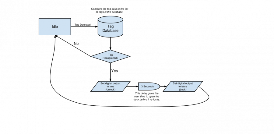
We need to have code that checks RFID tag events against a list or database of accepted tags and if the tag is a recognized tag, switch power on to the electric strike.
rfid.addTagGainListener(new TagGainListener()
{
	public void tagGained(TagGainEvent oe)
	{
		String line = null;
		try{
			reader = new Scanner(inFile); // set the scanner to read in from the appropriate file
		}
		catch(Exception e){}
		while(reader.hasNextLine()){  // read through the entire file
			try{
				line = reader.nextLine(); //read in the current tag data
				if(line.equals(oe.toString())){ //does the active tag match this entry?
					ik.setOutputState(0,true); //if so activate the relay.
				}
			}
			catch(Exception e){}
		}
		reader.close();
	}
});
Where inFile is a File object set to the file in which the tag data is stored. The tags can be read into a file off-line prior to normal operation, or at will with the push of a button depending on what you prefer. You can download the full code here. Note that this code has a mechanism for reading tags into a file though it is for demonstration purposes. In practice you would want the tag reading system to be a bit more robust. Perhaps by using a database of some kind so you could also log who specifically was accessing the door etc...
When the tag is no longer detected the door should relock, though we want to have a window in which the user can still open the door before it locks. This can be handled in our tag loss handler:
delay = new javax.swing.Timer(SHORTDELAY, new ActionListener(){  //SHORTDELAY is an arbitrary number of milliseconds
					public void actionPerformed(ActionEvent evt){
						try{
							ik.setOutputState(0,false);
						}
						catch(Exception e){}
						delay.stop();
					}
				});


rfid.addTagLossListener(new TagLossListener()
{
	public void tagLost(TagLossEvent oe)
	{
		try{
			if(ik.getOutputState(0) == true){
				delay.start();			//add a short delay so the user has time to open the door
			}
		}
		catch(Exception e){}
	}
});