|
Notice: This page contains information for the legacy Phidget21 Library. Phidget21 is out of support. Bugfixes may be considered on a case by case basis. Phidget21 does not support VINT Phidgets, or new USB Phidgets released after 2020. We maintain a selection of legacy devices for sale that are supported in Phidget21. We recommend that new projects be developed against the Phidget22 Library.
|
1131 User Guide: Difference between revisions
No edit summary |
|||
| Line 1: | Line 1: | ||
__NOINDEX__ | |||
[[Category:UserGuide]] | [[Category:UserGuide]] | ||
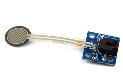
{{UserguideTOC|1131.jpg|1131}} | {{UserguideTOC|1131.jpg|1131}} | ||
Latest revision as of 14:34, 9 May 2018
| |
| Go to this device's product page |
Getting Started
Checking the Contents
|
You should have received:
|
In order to test your new Phidget you will also need:
| |
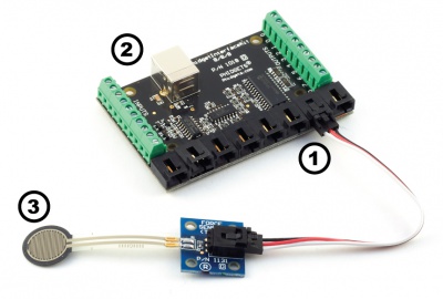
Connecting the Pieces
|
| |
Testing Using Windows 2000 / XP / Vista / 7
Make sure you have the current version of the Phidget library installed on your PC. If you don't, follow these steps:
- Go to the Quick Downloads section on the Windows page
- Download and run the Phidget21 Installer (32-bit, or 64-bit, depending on your system)
- You should see the
 icon on the right hand corner of the Task Bar.
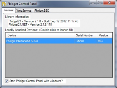
Running Phidgets Sample Program
Double clicking on the ![]() icon loads the Phidget Control Panel; we will use this program to ensure that your new Phidget works properly.
icon loads the Phidget Control Panel; we will use this program to ensure that your new Phidget works properly.
The source code for the InterfaceKit-full sample program can be found in the quick downloads section on the C# Language Page. If you'd like to see examples in other languages, you can visit our Languages page.
Updating Device Firmware
If an entry in this list is red, it means the firmware for that device is out of date. Double click on the entry to be given the option of updating the firmware. If you choose not to update the firmware, you can still run the example for that device after refusing.
|
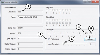
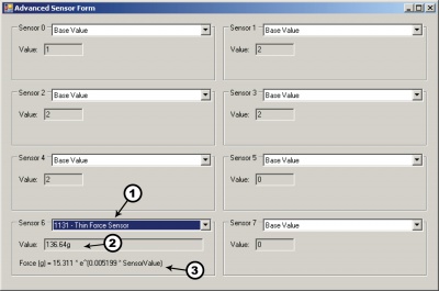
Double Click on the |
| |
sensitivity by moving the slider pointer.
|
| |
|
|
Testing Using Mac OS X
- Go to the Quick Downloads section on the Mac OS X page
- Download and run the Phidget OS X Installer
- Click on System Preferences >> Phidgets (under Other) to activate the Preference Pane
- Make sure that the is properly attached.
- Double Click on in the Phidget Preference Pane to bring up the Sample program. This program will function in a similar way as the Windows version.
Using Linux
For a step-by-step guide on getting Phidgets running on Linux, check the Linux page.
Using Windows Mobile / CE 5.0 / CE 6.0
For a step-by-step guide on getting Phidgets running on Windows CE, check the Windows CE page.
Technical Details
The Force Sensor can handle applied forces of up to 2 kg.
Formulas
The Formula to translate SensorValue into a force in grams is:

Measurement Accuracy
To ensure the most accuracy, a small disc (included) can be placed directly on the sensing pad before applying force to the disc. This will ensure that all the force is applied directly to the sensing pad and not to the surrounding surface. The longer the object rests on the sensing pad, the more the SensorValue will drift and increase slowly in value. It is very difficult to compensate for the drift since different constant forces will produce different drift rates. For this reason, the average accuracy of this sensor is within 10% of the true value. The formula above was determined after the object with a known mass was resting on the sensing pad for 15 seconds. The general drift rate curve is logarithmic with time.
Set up a Repeatable and Reproducible Mechanical Actuation System
- Provide a consistent force distribution. FSR response is very sensitive to the distribution of the applied force. In general, this precludes the use of dead weights for characterization since exact duplication of the weight distribution is rarely repeatable cycle-to-cycle. A consistent weight (force) distribution is more difficult to achieve than merely obtaining a consistent total applied weight (force). As long as the distribution is the same cycle-to-cycle, then repeatability will be maintained. The use of a thin elastomer between the applied force and the FSR can help absorb error from inconsistent force distributions.
- Keep the actuator area, shape, and compliance constant. Charges in these parameters significantly alter the response characteristic of a given sensor. Any test, mock-up, or evaluation conditions should be closely
matched to the final use conditions. The greater the cycle-to-cycle consistency of these parameters, the greater the device repeatability. In human interface applications where a finger is the mode of actuation, perfect control of these parameters is not generally possible. However, human force sensing is somewhat inaccurate; it is rarely sensitive enough to detect differences of less than ± 50%.
- Control actuator placement. In cases where the actuator is to be smaller than the FSR active area, cycle-tocycle consistency of actuator placement is necessary. (Caution: FSR layers are held together by an adhesive that surrounds the electrically active areas. If force is applied over an area which includes the adhesive, the resulting response characteristic will be drastically altered.) In an extreme case (e.g., a large, flat, hard actuator that bridges the bordering adhesive), the adhesive can present FSR actuation
- Keep actuation cycle time consistent. Because of the time dependence of the FSR resistance to an applied force, it is important when characterizing the sensor system to assure that increasing loads (e.g. force ramps) are applied at consistent rates (cycle-to-cycle). Likewise, static force measurements must take into account FSR mechanical setting time. This time is dependent on the mechanics of actuation and the amount of force applied and is usually on the order of seconds.
Develop a Nominal Voltage Curve and Error Spread
When a repeatable and reproducible system has been established, data from a group of FSR parts can be collected. Test several FSR parts in the system. Record the output voltage at various pre-selected force points throughout the range of interest. Once a family of curves is obtained, a nominal force vs. output voltage curve and the total force accuracy of the system can be determined.
Use Part Calibration if Greater Accuracy is Required
For applications requiring the highest obtainable force accuracy, part calibration will be necessary. Two methods can be utilized: gain and offset trimming, and curve fitting.
- Gain and offset trimming can be used as a simple method of calibration. The reference voltage and feedback resistor of the current-to-voltage converter are adjusted for each FSR to pull their responses closer to the nominal curve.
- Curve fitting is the most complete calibration method. A parametric curve fit is done for the nominal curve of a set of FSR devices, and the resultant equation is stored for future use. Fit parameters are then established for each individual FSR (or sending element in an array) in the set. These parameters, along with the measured sensor resistance (or voltage), are inserted into the equation to obtain the force reading. If needed, temperature compensation can also be included in the equation.
FSR Usage Tips - Do's and Dont's
- Do, if possible, use a firm, flat and smooth mounting surface.
- Do be careful if applying FSR devices to curved surfaces. Pre-loading of the device can occur as the two opposed layers are forced into contact by the bending tension. The device will still function, but the dynamic range may be reduced and resistance drift could occur. The degree of curvature over which an FSR can be bent is a function of the size of the active area. The smaller the active area, the less effect a given curvature will have on the FSR’s response.
- Do avoid air bubbles and contamination when laminating the FSR to any surface. Use only thin, uniform adhesives, such as Scotch® brand double-sided laminating adhesives. Cover the entire surface of the sensor.
- Do be careful of kinks or dents in active areas. They can cause false triggering of the sensors.
- Do protect the device from sharp objects. Use an overlay, such as a polycarbonate film or an elastomer, to prevent gouging of the FSR device.
- Do use soft rubber or a spring as part of the actuator in designs requiring some travel.
- Do not kink or crease the tail of the FSR device if you are bending it; this can cause breaks in the printed silver traces. The smallest suggested bend radius for the tails of evaluation parts is about 0.1” [2.5 mm]. In custom sensor designs, tails have been made that bend over radii of 0.03” (0.8 mm]. Also, be careful if bending the tail near the active area. This can cause stress on the active area and may result in pre-loading and false readings.
- Do not block the vent. FSR devices typically have an air vent that runs from the open active area down the length of the tail and out to the atmosphere. This vent assures pressure equilibrium with the environment, as well as allowing even loading and unloading of the device. Blocking this vent could cause FSRs to respond to any actuation in a non-repeatable manner. Also note, that if the device is to be used in a pressure chamber, the vented end will need to be kept vented to the outside of the chamber. This allows for the measurement of the differential pressure.
- Do not solder directly to the exposed silver traces. With flexible substrates, the solder joint will not hold and the substrate can easily melt and distort during the soldering. Use Interlink Electronics’ standard connection techniques, such as solderable tabs, housed female contacts, Z-axis conductive tapes, or ZIF (zero insertion force) style connectors.
- Do not use cyanoacrylate adhesives (e.g. Krazy Glue®) and solder flux removing agents. These degrade the substrate and can lead to cracking.
- Do not apply excessive shear force. This can cause delamination of the layers.
Other Interfacing Alternatives
If you want maximum accuracy, you can use the RawSensorValue property from the PhidgetInterfaceKit. To adjust a formula, substitute (SensorValue) with (RawSensorValue / 4.095) If the sensor is being interfaced to your own Analog to Digital Converter and not a Phidget device, our formulas can be modified by replacing (SensorValue) with (Vin * 200). It is important to consider the voltage reference and input voltage range of your ADC for full accuracy and range.
|
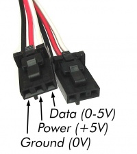
Each Analog Input uses a 3-pin, 0.100 inch pitch locking connector. Pictured here is a plug with the connections labelled. The connectors are commonly available - refer to the Analog Input Primer for manufacturer part numbers. |
| |
API
Phidget analog sensors do not have their own API- they simply output a voltage that is converted to a digital value and accessed through the "Sensor" properties and events on the PhidgetInterfaceKit API. It is not possible to programmatically identify which sensor is attached to the Analog Input. To an InterfaceKit, every sensor looks the same. Your application will need to apply formulas from this manual to the SensorValue (an integer that ranges from 0 to 1000) to convert it into the units of the quantity being measured. For example, this is how you would use a temperature sensor in a C# program:
 // set up the interfacekit object
InterfaceKit IFK = new InterfaceKit();

// link the new interfacekit object to the connected board
IFK.open("localhost", 5001);

// Get sensorvalue from analog input zero
int sensorvalue = IFK.sensors[0].Value;

// Convert sensorvalue into temperature in degrees Celsius
double roomtemp = Math.Round(((sensorvalue * 0.22222) - 61.11), 1);
See the PhidgetInterfaceKit User Guide for more information on the API and a description of our architecture.
For more code samples, find your preferred language on the Languages page.
Product History
| Date | Board Revision | Device Version | Comment |
|---|---|---|---|
| May 2010 | 0 | N/A | Product Release |