|
Notice: This page contains information for the legacy Phidget21 Library. Phidget21 is out of support. Bugfixes may be considered on a case by case basis. Phidget21 does not support VINT Phidgets, or new USB Phidgets released after 2020. We maintain a selection of legacy devices for sale that are supported in Phidget21. We recommend that new projects be developed against the Phidget22 Library.
|
1102 User Guide: Difference between revisions
No edit summary |
|||
| Line 1: | Line 1: | ||
[[Category:UserGuide]] | [[Category:UserGuide]] | ||
{{UserguideTOC|1102.jpg|1102}} | |||
==Getting Started== | ==Getting Started== | ||
Revision as of 15:23, 10 August 2012
| |
| Go to this device's product page |
Getting Started
Checking the Contents
|
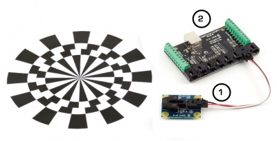
You should have received:
|
In order to test your new Phidget you will also need:
| |
Connecting the Pieces
|
| |
Testing Using Windows 2000 / XP / Vista / 7
Make sure you have the current version of the Phidget library installed on your PC. If you don't, follow these steps:
- Go to the Quick Downloads section on the Windows page
- Download and run the Phidget21 Installer (32-bit, or 64-bit, depending on your system)
- You should see the
 icon on the right hand corner of the Task Bar.
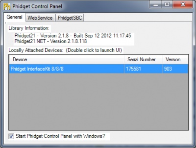
Running Phidgets Sample Program
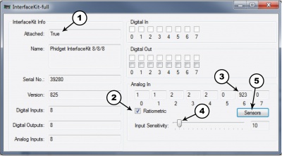
Double clicking on the ![]() icon loads the Phidget Control Panel; we will use this program to ensure that your new Phidget works properly.
icon loads the Phidget Control Panel; we will use this program to ensure that your new Phidget works properly.
The source code for the InterfaceKit-full sample program can be found in the quick downloads section on the C# Language Page. If you'd like to see examples in other languages, you can visit our Languages page.
Updating Device Firmware
If an entry in this list is red, it means the firmware for that device is out of date. Double click on the entry to be given the option of updating the firmware. If you choose not to update the firmware, you can still run the example for that device after refusing.
|
Double Click on the |
| |
|
| |
|
|
Testing Using Mac OS X
- Go to the Quick Downloads section on the Mac OS X page
- Download and run the Phidget OS X Installer
- Click on System Preferences >> Phidgets (under Other) to activate the Preference Pane
- Make sure that the Phidget InterfaceKit 8/8/8 is properly attached.
- Double Click on Phidget InterfaceKit 8/8/8 in the Phidget Preference Pane to bring up the InterfaceKit-full Sample program. This program will function in a similar way as the Windows version.
Using Linux
For a step-by-step guide on getting Phidgets running on Linux, check the Linux page.
Using Windows Mobile / CE 5.0 / CE 6.0
For a step-by-step guide on getting Phidgets running on Windows CE, check the Windows CE page.
Technical Details
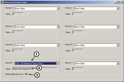
The Infrared sensor can detect an object at 5mm. It measures the amount of energy from the object and returns a value between 0 and 1000. A returned value between 0 and 400 signifies that the object has been detected. Values over 400 indicate that there is no reflective object within range, or that an object is too close.
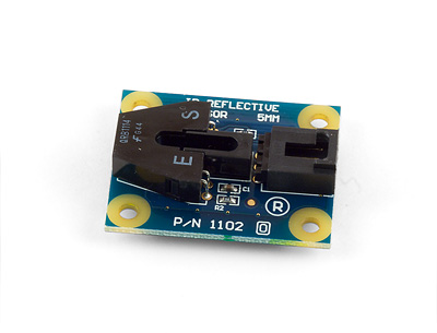
The 1102 sensor consists of an infrared emitting diode and an NPN silicon phototransistor mounted side by side on a converging optical axis in a black plastic housing. The phototransistor responds to radiation from the emitting diode only when a reflective object passes within its field of view. The area of the optimum response approximates a circle 5mm in diameter.
The amount of reflectivity is measured by Infrared and some materials that look very reflective to the human eye might not be as reflective in the infrared spectrum. The sensor can only detect objects that are between 3 to 7 mm away; it cannot see any objects outside that range.
The 1102 is not a digital sensor. The returned value is inversely proportional to the amount of reflectivity of the object (0 being more reflective, and 400 being less reflective), but in practice the variation between sensors is broad enough that the 1102 should not be used to measure the reflectivity of an object - only to detect if the object exists.
When working with sensors that are not digital, it is helpful to filter out noise by implementing a simple hysteresis in your code. By interpreting any SensorValue < 400 as a detection, and not releasing the detection until SensorValue goes above some higher threshold, such as 500, multiple triggering can often be avoided.
Finally, the 1102 works best in a constrained environment, where objects can be mechanically guaranteed to be within the 3-7mm range, or not present at all. The 1103 is a better choice as a general purpose “bump” sensor or human interface.
Other Interfacing Alternatives
If you want maximum accuracy, you can use the RawSensorValue property from the PhidgetInterfaceKit. To adjust a formula, substitute (SensorValue) with (RawSensorValue / 4.095) If the sensor is being interfaced to your own Analog to Digital Converter and not a Phidget device, our formulas can be modified by replacing (SensorValue) with (Vin * 200). It is important to consider the voltage reference and input voltage range of your ADC for full accuracy and range.
|
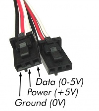
Each Analog Input uses a 3-pin, 0.100 inch pitch locking connector. Pictured here is a plug with the connections labelled. The connectors are commonly available - refer to the Analog Input Primer for manufacturer part numbers. |
| |
API
We document API Calls specific to this product in this section. Functions common to all Phidgets and functions not applicable to this device are not covered here. This section is deliberately generic. For calling conventions under a specific language, refer to the associated API manual in the Quick Downloads section for that language. For exact values, refer to the device specifications.
Data Structures
Functions
Events
Product History
| Date | Board Revision | Device Version | Comment |
|---|---|---|---|
| October 2005 | 0 | N/A | Product Release |