|
Notice: This page contains information for the legacy Phidget21 Library. Phidget21 is out of support. Bugfixes may be considered on a case by case basis. Phidget21 does not support VINT Phidgets, or new USB Phidgets released after 2020. We maintain a selection of legacy devices for sale that are supported in Phidget21. We recommend that new projects be developed against the Phidget22 Library.
|
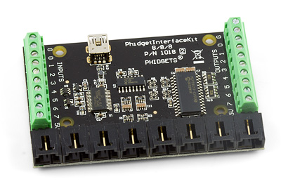
1018 User Guide
| |
| Go to this device's product page |
Getting Started
Checking the Contents
|
You should have received:
|
In order to test your new Phidget you will also need:
| |
Connecting the Pieces
|
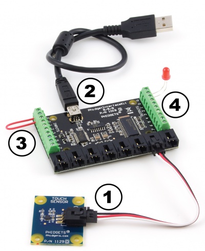
| |
Testing Using Windows 2000 / XP / Vista / 7
Make sure you have the current version of the Phidget library installed on your PC. If you don't, follow these steps:
- Go to the Quick Downloads section on the Windows page
- Download and run the Phidget21 Installer (32-bit, or 64-bit, depending on your system)
- You should see the
 icon on the right hand corner of the Task Bar.
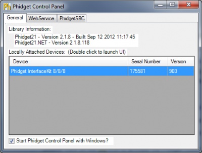
Running Phidgets Sample Program
Double clicking on the ![]() icon loads the Phidget Control Panel; we will use this program to ensure that your new Phidget works properly.
icon loads the Phidget Control Panel; we will use this program to ensure that your new Phidget works properly.
The source code for the InterfaceKit-full sample program can be found in the quick downloads section on the C# Language Page. If you'd like to see examples in other languages, you can visit our Languages page.
Updating Device Firmware
If an entry in this list is red, it means the firmware for that device is out of date. Double click on the entry to be given the option of updating the firmware. If you choose not to update the firmware, you can still run the example for that device after refusing.
|
Double Click on the |
| |
|
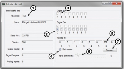
| |
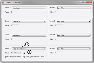
Note: If you have connected a sensor that uses a formula, the calculated value and the formula are displayed under the drop down menu. |
|
Testing Using Mac OS X
- Go to the Quick Downloads section on the Mac OS X page
- Download and run the Phidget OS X Installer
- Click on System Preferences >> Phidgets (under Other) to activate the Preference Pane
- Make sure that the Phidget InterfaceKit 8/8/8 is properly attached.
- Double Click on Phidget InterfaceKit 8/8/8 in the Phidget Preference Pane to bring up the InterfaceKit-full Sample program. This program will function in a similar way as the Windows version.
Using Linux
For a step-by-step guide on getting Phidgets running on Linux, check the Linux page.
Using Windows Mobile / CE 5.0 / CE 6.0
For a step-by-step guide on getting Phidgets running on Windows CE, check the Windows CE page.
Technical Details
If you want to know more about the input/output capabilities of the 1018 InterfaceKit, check the Digital Input Primer, Digital Input Primer, and the Analog Input Primer.
API
We document API Calls specific to this product in this section. Functions common to all Phidgets and functions not applicable to this device are not covered here. This section is deliberately generic. For calling conventions under a specific language, refer to the associated API manual in the Quick Downloads section for that language. For exact values, refer to the device specifications.
Functions
int InputCount() [get] : Constant = 8
- Returns the number of digital inputs supported by this PhidgetInterfaceKit.
bool InputState(int InputIndex) [get]
- Returns the state of a particular digital input. Digital inputs read True where they are activated and false when they are in their default state.
int OutputCount() [get] : Constant = 8
- Returns the number of digital outputs supported by this PhidgetInterfaceKit.
bool OutputState (int OutputIndex) [get,set]
- Sets/returns the state of a digital output. Setting this to true will activate the output, False is the default state. Reading the OutputState immediately after setting it will not return the value set - it will return the last state reported by the Phidget.
int SensorCount() [get] : Constant = 8
- Returns the number of sensors (Analog Inputs) supported by this PhidgetInterfaceKit. Note that there is no way of determining is a sensor is attached, and what sensor is attached.
int SensorValue(int SensorIndex) [get]
- Returns the sensed value of a particular Analog Input. SensorValue varies between 0-1000, corresponding to the 0-5V input range of the Analog Input. If you are using an Analog Sensor from Phidgets Inc., it’s manual will specify the formula used to convert SensorValue into the measured property.
int SensorRawValue (int SensorIndex) [get]
- Returns the full resolution of the Analog Input. This is a more accurate version of SensorValue. The valid range is 0-4095. Note however that the analog outputs on the Interface Kit 8/8/8 are only 10-bit values and this value represents an oversampling to 12-bit.
double SensorChangeTrigger (int SensorIndex) [get,set]
- Returns the change trigger for an analog input. This is the amount that an inputs must change between successive SensorChangeEvents. This is based on the 0-1000 range provided by getSensorValue. This value is by default set to 10 for most Interface Kits with analog inputs. SensorChangeTrigger is sometimes referred to as sensitivity.
int DataRate (int SensorIndex) [get,set]
- Gets/sets the data rate for an analog input. This is corresponds to the fastest rate at which SensorChange events will be fired. The data rate is superseded by SensorChangeTrigger, which can be set to 0 if a constant data rate is required. Data Rate is in milliseconds and corresponds to the amount of time between events. Data Rate is bounded by DataRateMax and DataRateMin. The analog inputs cannot all be set to the fastest data rate at the same time - if this is attempted, an exception will be thrown when the data bandwidth has been exceeded. For data rates less then the maximum, data is still sampled at the maximum speed, and averaged between events for the user. Supported data rates are: 1, 2, 4, 8, and every multiple of 8 until DataRateMin. Setting an unsupported data rate (ie. 3, 9, 17) will result in a thrown exception. Note that data rate is limited to 16ms when opening over the Phidget Webservice.
int DataRateMax (int SensorIndex) [get]
- The maximum data rate that can be set for an analog input, in milliseconds.
int DataRateMin (int SensorIndex) [get]
- The minimum data rate that can be set for an analog input, in milliseconds. This is usually 1000.
bool Ratiometric() [get,set]
- Sets/returns the state of Ratiometric. Ratiometric = true configures the Analog Inputs to measure relative to VCC (nominal 5V). Ratiometric = false configures the Analog Inputs to measure relative to an internal precision 5V reference. Ratiometric is not updated from the Phidget. It is recommended to explicitly set Ratiometric when the Interfacekit is opened. After changing the ratiometric state, wait until the ratiometric property matches what was set before reading analog data.
Events
OnInputChange(int InputIndex, bool State) [event]
- An event that is issued when the state of a digital input changes.
OnOutputChange(int OutputIndex, bool State), [event]
- An event that is issued when the state of a digital output changes.
OnSensorChange(int SensorIndex, int SensorValue), [event]
- An event that is issued when the returned value from a sensor (Analog Input) varies by more than the SensorChangeTrigger property.
Product History
| Date | Board Revision | Device Version | Comment |
|---|---|---|---|
| July 2007 | 0 | 824 | Product Release |
| September 2007 | 0 | 825 | SPI Overclocking issue fixed |
| May 2008 | 1 | 826 | Added RC Filtering to Digital Inputs, PCB X Dimension increased to 3.27” |
| April 2010 | 2 | 900 | Configurable data sampling speed. Replace USB connector with Mini-USB connector |