Template:UgDigitalInputISA: Difference between revisions
From Phidgets Support
| Line 7: | Line 7: | ||
* At the top of the window, information about your device and the properties of this particular channel will be listed. | * At the top of the window, information about your device and the properties of this particular channel will be listed. | ||
* In the middle, there is a box that will display "true" or "false" depending on the state of the digital input. Be sure you select the proper mode (NPN / PNP) for your particular sensor. If you have a switch, you can test this input by connecting the digital input terminal of the sensor to one of the switch's terminals, and the sensor's ground terminal to another. Pressing the switch should cause the input to read "true". | * In the middle, there is a box that will display "true" or "false" depending on the state of the digital input. Be sure you select the proper mode (NPN / PNP) for your particular sensor. If you have a switch, you can test this input by connecting the digital input terminal of the sensor to one of the switch's terminals, and the sensor's ground terminal to another. Pressing the switch should cause the input to read "true". | ||
* At the bottom of the window, there is a selection for the power supply. The power supply setting must be set to the voltage expected by the sensor connected to the adapter. | |||
<br clear="all"> | <br clear="all"> | ||
Revision as of 15:52, 8 June 2017
Digital Input
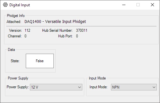
When you double click on an Digital Input object, a window like the one pictured will open.
- At the top of the window, information about your device and the properties of this particular channel will be listed.
- In the middle, there is a box that will display "true" or "false" depending on the state of the digital input. Be sure you select the proper mode (NPN / PNP) for your particular sensor. If you have a switch, you can test this input by connecting the digital input terminal of the sensor to one of the switch's terminals, and the sensor's ground terminal to another. Pressing the switch should cause the input to read "true".
- At the bottom of the window, there is a selection for the power supply. The power supply setting must be set to the voltage expected by the sensor connected to the adapter.