TMP1200 User Guide: Difference between revisions
No edit summary |
No edit summary |
||
| (6 intermediate revisions by 2 users not shown) | |||
| Line 1: | Line 1: | ||
__NOINDEX__ | |||
<metadesc>Measure RTDs, thermistors, and other resistance-based sensors with the RTD Phidget. Connects to a port on your VINT Hub.</metadesc> | |||
[[Category:UserGuide]] | [[Category:UserGuide]] | ||
===Getting Started=== | |||
{{UGIntro|TMP1200}} | |||
== | |||
* | * [{{SERVER}}/products.php?product_id=TMP1200 TMP1200 RTD Phidget] | ||
* | * {{VINTHub}} | ||
* | * {{CT|PhidgetCable|Phidget cable}} | ||
* | * USB cable and computer | ||
* platinum RTD | |||
* | |||
Next, you will need to connect the pieces: | |||
[[Image:TMP1200-functional.jpg|500px|link=|right]] | |||
# Connect the TMP1200 to the VINT Hub using the Phidget cable. | # Connect the TMP1200 to the VINT Hub using the Phidget cable. | ||
# Connect the RTD to the Phidget. See the [[#Technical_Details|technical section]] for more information. | # Connect the RTD to the Phidget. See the [[#Technical_Details|technical section]] for more information. | ||
| Line 19: | Line 19: | ||
<br clear="all"> | <br clear="all"> | ||
== | ==Using the TMP1200== | ||
{{UGcontrolpanel|TMP1200}} | {{UGcontrolpanel|TMP1200}} | ||
| Line 26: | Line 26: | ||
{{ugRTDInput}} | {{ugRTDInput}} | ||
{{ | {{ugAddressingInformation}} | ||
{{ugUsingYourOwnProgram|TMP1200}} | |||
==Technical Details== | ==Technical Details== | ||
Revision as of 16:36, 17 October 2019
Getting Started
Welcome to the TMP1200 user guide! In order to get started, make sure you have the following hardware on hand:
- TMP1200 RTD Phidget
- VINT Hub
- Phidget cable
- USB cable and computer
- platinum RTD
Next, you will need to connect the pieces:
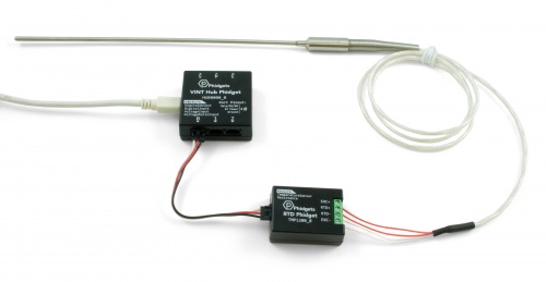
- Connect the TMP1200 to the VINT Hub using the Phidget cable.
- Connect the RTD to the Phidget. See the technical section for more information.
- Connect the VINT Hub to your computer with a USB cable.
Using the TMP1200
Phidget Control Panel
In order to demonstrate the functionality of the TMP1200, the Phidget Control Panel running on a Windows machine will be used.
The Phidget Control Panel is available for use on both macOS and Windows machines.
Windows
To open the Phidget Control Panel on Windows, find the ![]() icon in the taskbar. If it is not there, open up the start menu and search for Phidget Control Panel
icon in the taskbar. If it is not there, open up the start menu and search for Phidget Control Panel
macOS
To open the Phidget Control Panel on macOS, open Finder and navigate to the Phidget Control Panel in the Applications list. Double click on the ![]() icon to bring up the Phidget Control Panel.
icon to bring up the Phidget Control Panel.
For more information, take a look at the getting started guide for your operating system:
Linux users can follow the getting started with Linux guide and continue reading here for more information about the TMP1200.
First Look
After plugging the TMP1200 into your computer and opening the Phidget Control Panel, you will see something like this:
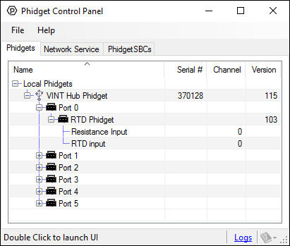
The Phidget Control Panel will list all connected Phidgets and associated objects, as well as the following information:
- Serial number: allows you to differentiate between similar Phidgets.
- Channel: allows you to differentiate between similar objects on a Phidget.
- Version number: corresponds to the firmware version your Phidget is running. If your Phidget is listed in red, your firmware is out of date. Update the firmware by double-clicking the entry.
The Phidget Control Panel can also be used to test your device. Double-clicking on an object will open an example.
Resistance Input
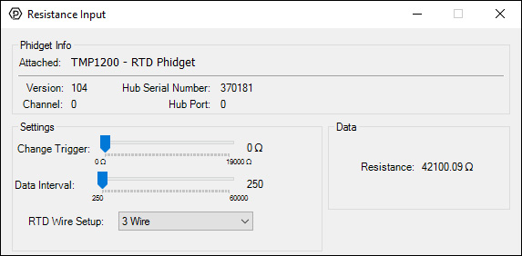
When you double click on an Resistance Input object, a window like the one pictured will open.
- At the top of the window, information about your device and the properties of this particular channel will be listed.
- On the left, change trigger and/or data interval can be changed. For more information on these settings, see the Data Rate/Change Trigger page. You can also select the type of wiring setup you're using to connect the RTD.
- On the right, the current reading of the resistance is listed in ohms.
RTD Input
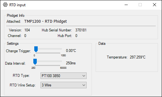
When you double click on an RTD Input object, a window like the one pictured will open.
- At the top of the window, information about your device and the properties of this particular channel will be listed.
- On the left, change trigger and/or data interval can be changed. For more information on these settings, see the Data Rate/Change Trigger page. You can also select the RTD type and the wiring setup to automatically calculate the temperature from the sensor reading.
- On the right, the current reading of the temperature is listed in degrees Celsius.
Finding The Addressing Information
Before you can access the device in your own code, and from our examples, you'll need to take note of the addressing parameters for your Phidget. These will indicate how the Phidget is physically connected to your application. For simplicity, these parameters can be found by clicking the button at the top of the Control Panel example for that Phidget.

In the Addressing Information window, the section above the line displays information you will need to connect to your Phidget from any application. In particular, note the Channel Class field as this will be the API you will need to use with your Phidget, and the type of example you should use to get started with it. The section below the line provides information about the network the Phidget is connected on if it is attached remotely. Keep track of these parameters moving forward, as you will need them once you start running our examples or your own code.

Using Your Own Program
You are now ready to start writing your own code for the device. The best way to do that is to start from our Code Samples.
Select your programming language of choice from the drop-down list to get an example for your device. You can use the options provided to further customize the example to best suit your needs.
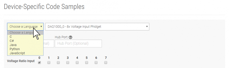
Once you have your example, you will need to follow the instructions on the page for your programming language to get it running. To find these instructions, select your programming language from the Programming Languages page.
Technical Details
Wiring Modes
Two-Wire Mode
This is the simplest wiring setup for an RTD, but also the least accurate because the resistance of the leads are not taken into account. To connect a 2-wire RTD to the RTD Phidget, connect one wire to the RTD+ terminal, and the other to the RTD- terminal. Then connect the EXC+ terminal to the RTD+ terminal and the EXC- to the RTD- terminal with two short wires.
In your program, set RTDWireSetup to 2-wire mode. In the Phidget22 API select the TMP1200 and your programming language of choice to see exact naming conventions.
Three-Wire Mode
In a three-wire RTD, the extra wire is added to measure the resistance of one of the leads. This calculation assumes that both leads have the same resistance. Your RTD should have two wires that share a color; connect one of these wires to the RTD- terminal and the other to the EXC- terminal. The differently colored wire connects to the RTD+ terminal. Then connect the EXC+ terminal to the RTD+ terminal with a short wire.
In your program, set RTDWireSetup to 3-wire mode. In the Phidget22 API select the TMP1200 and your programming language of choice to see exact naming conventions.
Four-Wire Mode
A four-wire RTD is normally used in precision measurement, when the assumption that both leads have the same resistance is not accurate enough. Unfortunately the RTD Phidget does not support this particular feature of four-wire RTDs. It does, however, support the use of four-wire RTDs using the same assumption as three-wire mode. To connect a four-wire RTD, simply connect one pair of same-colored wires to the RTD+ and EXC+ terminals, and the other pair to the RTD- and EXC- terminals.
In your program, set RTDWireSetup to 4-wire mode. In the Phidget22 API select the TMP1200 and your programming language of choice to see exact naming conventions.
Line Resistance Measurement
In three and four wire modes, this device will measure the line resistance every 5 minutes. This measurement will cause a delay in measurement for data intervals of less than 500ms. To force the line resistance to be recalculated, you must close and re-open the device.
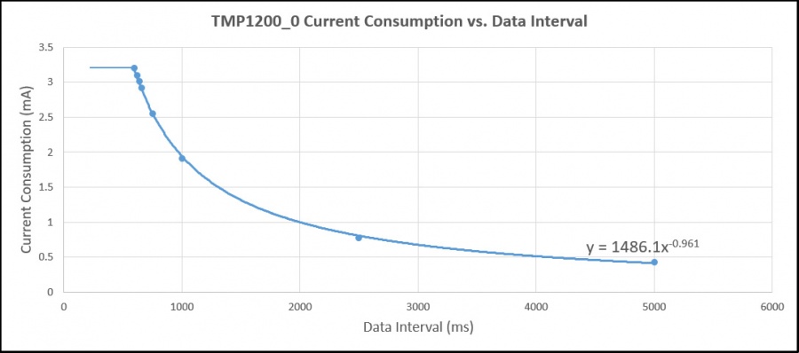
Current Consumption
The amount of current consumed by the TMP1200 depends on the DataInterval being used:
What to do Next
- Programming Languages - Find your preferred programming language here and learn how to write your own code with Phidgets!
- Phidget Programming Basics - Once you have set up Phidgets to work with your programming environment, we recommend you read our page on to learn the fundamentals of programming with Phidgets.