SBC3003 User Guide
Welcome
Welcome to the user guide for the SBC3003. In this guide we will introduce you to your new Phidget and show you what it is capable of. To get started, make sure you have the following things available:
- Your new SBC3003
- An Ethernet cable and a 6-15VDC power supply (both included with SBC3003)
- A Phidget or Phidget sensor
- A computer
Ready? Then let's get started!
Getting Started
Follow the steps below:
- Plug in any Phidgets or Phidget sensors you have to the SBC.
- Connect your SBC to your network using the Ethernet cable.
- Connect your SBC to power. A red LED should immediately light up underneath the power barrel, indicating your SBC is receiving power. There is also a green LED that will briefly turn on when power is supplied, and then remain on after the SBC has fully booted.
The next step will be to access the SBC Web Interface. This process will vary slightly depending on what type of computer you use:
Using a Windows machine? Keep reading.
Windows
First things first: make sure you have the latest Phidget drivers installed on your machine. Download and run the installer:
Now that you have the drivers installed, find the ![]() icon in the taskbar. If it is not there, open up the start menu and search for Phidget Control Panel
icon in the taskbar. If it is not there, open up the start menu and search for Phidget Control Panel
Double click on the icon to open the Phidget Control Panel and navigate to the PhidgetSBCs tab:
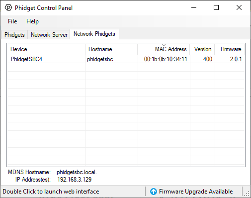
As shown in the image above, the Phidget Control Panel will relay the following information to you:
- The default link local address (mDNS address) which is phidgetsbc.local
- The IP address. There is no default IP address, it must be assigned to the SBC.
- The MAC address. This is useful for distinguishing between multiple SBCs.
Next, double-click on your SBC in the Phidget Control Panel. This will automatically open the SBC Web Interface, which, conveniently enough, is our next topic! Jump ahead to the SBC Web Interface.
macOS
First things first: make sure you have the latest Phidget drivers installed on your machine. Download and run the installer:
Now that you have the drivers installed, find the Phidget Control Panel. There should be an icon in your Applications folder that looks like this: ![]()
Open the Phidget Control Panel application and navigate to the PhidgetSBCs tab:
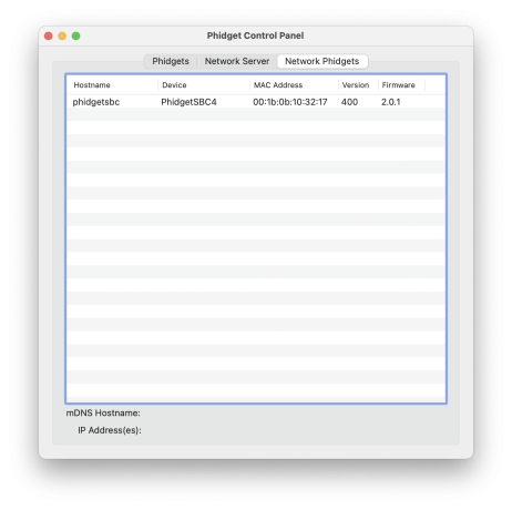
As shown in the image above, the Phidget Control Panel will relay the following information to you:
- The default link local address (mDNS hostname) which is phidgetsbc.local
- The IP address. There is no default IP address, it must be assigned to the SBC.
- The MAC address. This is useful for distinguishing between multiple SBCs.
Next, double-click on your SBC in the Phidget Control Panel. This will automatically open the SBC Web Interface, which, conveniently enough, is our next topic! Jump ahead to the SBC Web Interface.
Linux
WAITING FOR PHIDGET22ADMIN TOOL
SBC Web Interface
The SBC Web Interface is a powerful tool that will prove invaluable when you begin development. You opened the SBC Web Interface in the previous step, so let`s jump right in and set a password!
Setting a password
The first time you open the SBC Web Interface, you will be greeted with this screen:
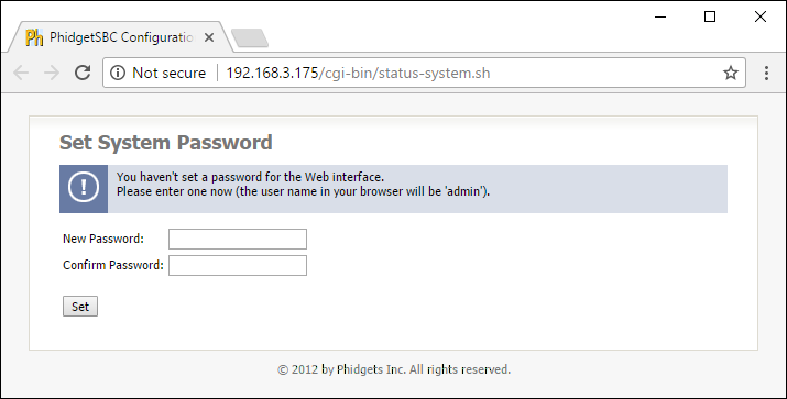
You will use this password in the following situations:
- Future SBC Web Interface access (linked to user admin)
- SBC terminal access (linked to user root)
Take a look around
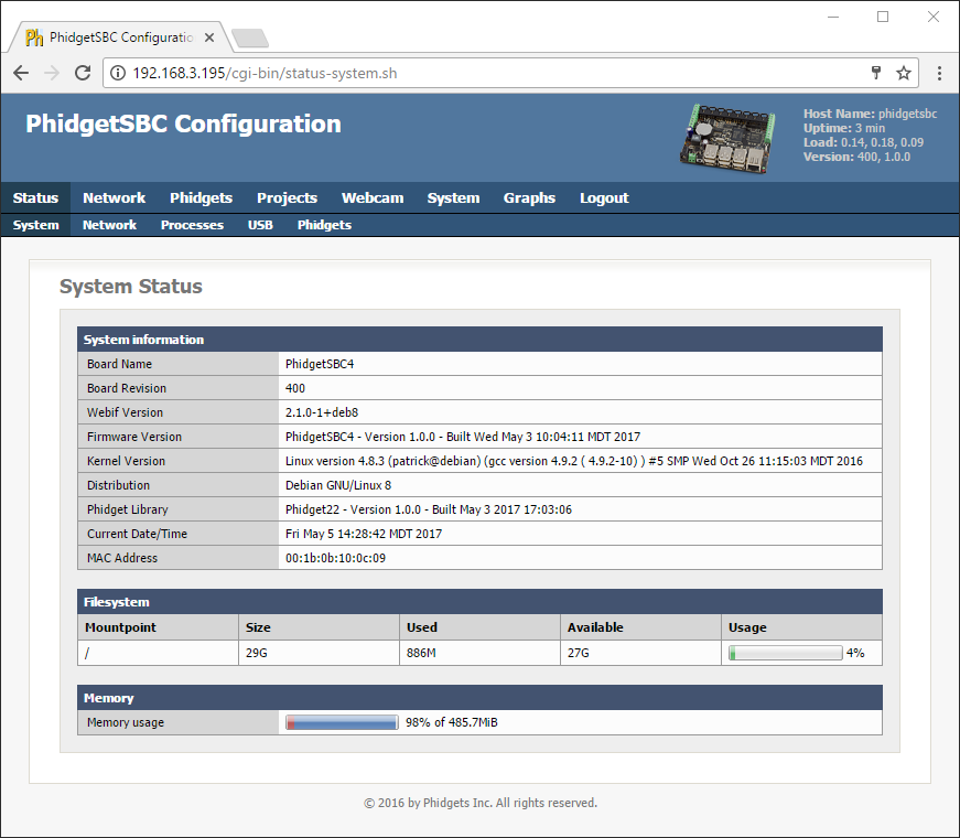
Welcome to the SBC homepage! Here you can view system information such as the firmware version, the amount of storage you have left, and more. Take a minute to look around, and when you're ready, we will give an overview of the SBC Web Interface, starting with networking.
Set up Networking
You can connect to your network in two ways with the SBC:
- via an Ethernet cable
- via a Wi-Fi USB adapter (we recommend this one)
The SBC can switch between these connections on the fly and will try to connect to Ethernet first. If you're following this guide, you've already set up your network using an Ethernet cable by simply plugging it in. Next, we will take a look at setting up Wi-Fi.
Wireless
To set up Wi-Fi on the SBC, first plug in your Wi-Fi USB adapter. Next, navigate to Network->Wireless and your screen will look something like this:
Add your Wi-Fi network by selecting it from the list, providing any necessary credentials, and clicking the Add This Network button.
Here are some useful Wi-Fi tips:
- You don't have to see a network in order to connect to it. You can add the SSID and password of a network, and the next time the SBC boots it will connect to that network if it is available.
- The SSID settings are only for DHCP networks.
Next, we will cover setting a static IP with the SBC Web Interface.
Static IP
Don't have DHCP on your main network? Not to worry, you can easily set up a static IP with the SBC:
- Ethernet: Navigate to Network->Settings to set up a static IP.
- Wi-Fi: Navigate to Network->Wireless to set up a static IP.
Now simply enter your network configuration and save the changes. The SBC will immediately start to use the static IP.
Warning: setting a static IP improperly can make the SBC very hard to re-connect to depending on the routing within the rest of your network.
View Attached Phidgets
Phidgets Status
Now that your networking is set up, let's take a look at which Phidgets are attached to the SBC. Do this by navigating to Phidgets->Status. Your screen should look something like this:
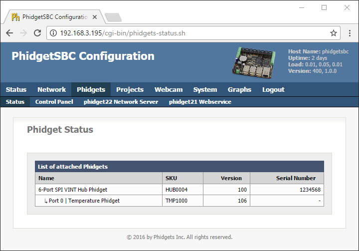
Notes about attached Phidgets:
- The SBC has a built in VINT Hub Phidget, so you will always see it on your list of attached Phidgets.
- If you have an analog sensor, it will not show up on the list of attached Phidgets.
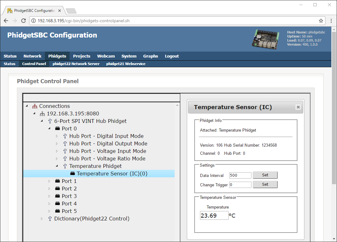
Control Panel
After you confirm which Phidgets are attached to your SBC, navigate to Phidgets->Control Panel. Here, you can test your Phidgets and learn more about their functionality.
Using a Webcam
If you would like to use a webcam with the SBC, ensure it is a UVC (USB Video Class) compatible webcam that supports MJPEG. Next, simply plug it into the SBC and navigate to the Webcam tab.
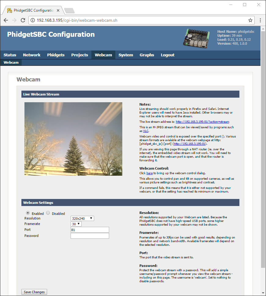
Take a minute to play around with the different resolutions and framerates available. Also, be sure to check out the webcam control dialog shown below:
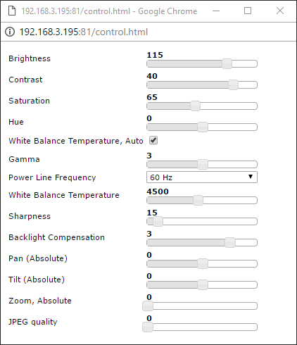
Notes about using a webcam:
- When using a password, the username is webcam. It is recommended to add a password if you are planning to share the stream, however, the HTTP authentication is sent unencrypted, so it is not very secure.
- If multiple webcams are attached, they will start up with the same settings (port number will be incremented for each one). When using multiple webcams, resolution and framerates will have to be reduced.
Technical Details
Rebooting/Resetting the PhidgetSBC
To reboot the device, quickly press the black reset button found between the USB connectors and the power terminals. Both Ethernet Port LEDs (yellow-connectivity, green-activity), and the green status LED will turn off. The reboot is done when all LEDs come back on in about 25 seconds.
To reset the firmware, press and hold the button for 10 seconds until the green status LED begins to blink, then release. Both Ethernet Port LEDs will turn off (yellow-connectivity, green-activity) for 80 seconds; the green status LED will then turn off; then all LEDs will come back on in 20 seconds. All data will be lost and the operating system will be reset to a factory state.
To boot into the Recovery / Upgrade system, hold the button for 20 seconds until the green status LED switches from blinking slowly to blinking quickly, then release. The recovery system allows for factory reset, full system upgrades and recovery of the main system.
Recovery / Upgrade System
The recovery / upgrade system is a small system from which the main system can be reset/upgraded, or recovered.
Entering the Recovery System
The recovery system can be entered in two ways.
- From the ‘System: Backup & Restore’ web interface page.
- By holding down the reset button for 20+ seconds - until the green light has switched from flashing slowly to flashing quickly.
Upgrades
Generally, you should not need to do a full system upgrade. Upgrades are meant to be performed via the package system, and Phidgets maintains it’s own package repository from which to push out updates.
Occasionally, you may wish to go back to a clean install and upgrade to the latest rootfs/kernel from Phidgets. Phidgets will not be creating these images with every release of phidget21 as we did with PhidgetSBC1, rather they will be released several times a year, as needed for major changes not easy to push out via packages.
You can also flash your own custom kernel or root filesystem image.
Factory Reset
This restores the kernel and root filesystem from backup, overwriting any changes that may have been made. This is equivalent to holding down the reset button for 10 seconds.
Recovery
If the main filesystem has been damaged/misconfigured in such a way that it won’t boot, you may be able to fix the issue / recovery important files before running a reset. The recovery system runs an SSH server that you can loginto for console access. Username/password is: root/root.
You can mount the main root filesystem with the following commands (assuming it’s not damaged):
- ubiattach /dev/ubi_ctrl -m 6
- mount -t ubifs /dev/ubi0_0 /mnt
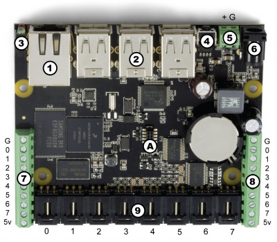
Ports and Connectors
|
Numbered in the circles on the diagram:
|
| |
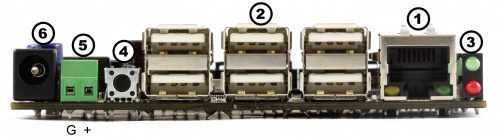
- 1. This Ethernet port is used for network connectivity to the PhidgetSBC. This enables access to the PhidgetSBC as well as any connected Phidgets through the network server. Alternatively, the USB Wireless adapter can be used for network connectivity.
- 2. These USB ports can be used for connecting Phidgets, Wi-Fi adapters, flash drives, webcams, USB hubs, etc.
- 3. These LEDs indicate the status of the PhidgetSBC. The Red LED indicates that the power supply is on and running properly. The green LED indicates boot status. The green LED will turn on and off once during boot and then turn back on when everything is running.
- 4. This will reboot the board if pressed once. Note that this is a forced reboot. Any user programs that were running may leave their data in a inconsistent state, but this is safe for the base system. A soft reboot can be performed remotely from the configuration interface.If held for more then 10 seconds, the red LED will start to blink and enter emergency Reset mode. Once the button is released, the onboard memory will revert to a factory-fresh state. This includes overwriting the kernel and root file system, and erasing all configuration, user data, and applications. If held for more then 20 seconds, the Recovery/Upgrade system will be booted, from which a Factory Reset/Full filesystem upgrade can be performed.
- 5,6. The PhidgetSBC can be powered from either the terminals or the barrel connector.
- 7,8,9. The Interface Kit I/O is explained in the Interface Kit section of the manual.
Power Distribution
The 12V power supply is stepped down to 5V and distributed in the following way:
- Each USB port has 500 mA available
- All analog inputs share a total of 500 mA
- The digital outputs, +5V terminals, USB controller, and pull-ups all share a total of 500 mA
Power Over Ethernet
Power over Ethernet can be used to provide both a network connection and power to a device when a power outlet is not available. This means that with the proper adapters, you can run the PhidgetSBC entirely off an Ethernet source. The PhidgetSBC does not draw power directly from a powered Ethernet line, but instead can use a setup where the power is split to a separate line again near the PhidgetSBC. The board has been tested and will work with Power Sourcing Equipment that can output 6-12VDC.
Hardware Layout
The PhidgetSBC is based around the i.MX28 processor. This is an ARM926EJ-S based microprocessor from Freescale, which runs at 454MHz. Connected to this is 128 MiB of DDR2 SDRAM, 1 GiB of very large page NAND and a 10/100baseT Ethernet controller. The microprocessors USB Host port is connected to a 7-port USB 2.0 High Speed Hub chip. The integrated PhidgetInterfaceKit 8/8/8 is connected to one of the hub ports, with the other 6 ports being brought out to the user.
Software Layout
The PhidgetSBC runs Debian/GNU Linux 7.0 as its operating system and gets booted with U-Boot. The kernel is 3.6.3 and generally kept up to date with the latest releases. The root filesystem is created using debootstrap and is mounted in a ~924MiB nand partition using the UBIFS filesystem, in Read-Write mode.
Configuration data is located at ‘/etc/webif’. This is where all configuration that can be set through the website is located.
User applications are stored in ‘/usr/userapps’, each is their own directory.
The kernel is stored on bare Nand in it own 4MiB partition, in the uImage format.
Date and Time
The date and time are set using ntp (network time protocol) at boot. The ntp daemon continues to run in the background and will periodically update the clock, keeping it very close to real time.
There is a real-time clock with battery backup which will preserve date/time across reboots, power removal. The real-time clock is synced to system time during reboot/shutdown. If power is unplugged suddenly, the real-time clock may not have the correct time.
Wireless Networking System
Wireless networking is supported using the available adapter and is configured through the configuration interface.
Configuration System
The configuration system used by the website is stored in ‘/etc/webif’. These files should generally not be changed manually, but there is no reason why they could not be. It’s very easy to enter invalid data that could cause the system to behave unexpectedly or not boot.
Nand Layout
The board contains 1GiB of Nand. This nand is split into 8 partitions as follows:
| 0: bootloader | size: 4MiB | Read Only |
| 1: environment | size: 512KiB | Read Only |
| 2: device_tree | size: 512KiB | Read Only |
| 3: recovery_system | size: 4MiB | Read Only |
| 4: recovery_kernel | size: 4MiB | Read Only |
| 5: recovery_fs | size: 83MiB | Read Only |
| 6: kernel | size: 4MiB | Writable |
| 7: rootfs | size: 924MiB | Writable |
U-Boot and recovery kernel and filesystem cannot be written from Linux - this is a safety measure.
Boot Process
This describes the boot process from power on.
- CPU loads the bootstream from Nand
- Bootstream initializes memory, power and GPIO, then runs u-boot from Nand
- u-boot turns the green LED on and then checks to see if the reset button is being held down
- if the reset button is held, u-boot either restores the kernel/filesystem, or boot into the recovery system, depending on the hold time
- u-boot then loads the device tree and Linux kernel into Ram and then runs the kernel
- Linux reads in the device tree from ram, and turns off the green LED
- Linux then boots, bringing up usb, ethernet, etc.
- init gets run as the parents of all processes, and uses the /etc/inittab script to bring up the system. This includes mounting other filesystems, settings the hostname, running the scripts in /etc/init.d, and running user applications
- inittab then turns the green LED on. The system has finished booting
Drivers for USB to Serial adapters
The SBC kernel contains driver support for the following USB to Serial Adapters. Please consult the kernel documentation for details into the driver support for the USB to Serial adapters.
| Company | Product |
|---|---|
| ConnectTech | WhiteHEAT |
| Keyspan | USA-18X, USA-28, USA-28X, USA-28XA, USA-28XB, USA-19, USA-19W, USA-19QW, USA-19QI, USA-49W, USA-49WLC |
| FTDI | Single Port Serial Adapter |
| Cypress | M8 CY4601 Family |
| Digi International | AccelePort USB Serial |
| Belkin | USB Serial Adapter F5U103 |
| MCT | USB Single Port Serial Adapter U232 |
| Inside Out Networks | Edgeport Serial Adapter |
| Prolific | PL2303 |
Drivers for USB Wifi Adapters
The SBC kernel contains driver support for the following USB Wireless Adapters. Please consult the kernel documentation for more details.
| Company | Module | Chipsets |
|---|---|---|
| Atheros | ath9k_htc | AR9271, AR7010 |
| Atheros | carl9170 | AR9170 |
| Intersil | r8712u | ISL3877, ISL3880, ISL3886, ISL3887, ISL3890 |
| Realtek | r8712u | RTL8188SU, RTL8191SU, RTL8192SU |
| Ralink | rt2500usb | RT2500USB/RT2571 |
| Ralink | rt2800usb | RT2070, RT2770, RT2870, RT3070, RT3071, RT3072, RT3370, RT3572, RT5370, RT5372 |
| Ralink | rt73usb | RT2501USB/RT2571W |
| Realtek | rtl8187 | RTL8187L, RTL8187B |
| Realtek | rtl8192cu | RTL8188CUS, RTL8192CU |
| ZyDAS / Atheros | zd1211rw | ZD1211/ZD1211B, AR5007UG |
U-Boot
U-Boot is used for setting up the processor and booting Linux, and is only accessible by the serial port. Normal users will not need to use it. If you are connected to the serial port, you will see the U-Boot prompt shortly after power up. You can view the environment variables for information on how to properly boot Linux on the PhidgetSBC.
Be very careful when modifying the u-boot partition. If it is damaged or overwritten, it is difficult to fix.
Refer to U-Boot documentation here: www.denix.de/wiki/DULG/Manual for more information on using U-Boot.
Ad-hoc Networks
The SBC can be configured as a device in an ad-hoc network.
For more information, visit the Ad-Hoc Networks page.
Further Reading
Check the Phidget SBC page for more details about using the Phidget SBC.
Check the 1018 User Guide for more information about the InterfaceKit on this board.
What to do Next
- Programming Languages - Find your preferred programming language here and learn how to write your own code with Phidgets!
- Phidget Programming Basics - Once you have set up Phidgets to work with your programming environment, we recommend you read our page on to learn the fundamentals of programming with Phidgets.