Open Collector Digital Output Guide
Introduction
An Open Collector Digital Output behaves similarly to a Solid State Relay- by toggling the state of the output, you can switch a circuit on and off. This type of output does not supply power to the load like an ordinary Digital Output, it simply switches a powered circuit to ground.
How it Works
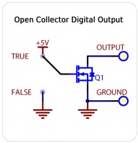
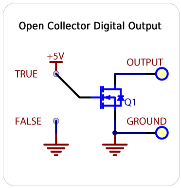
The Digital Outputs require an external voltage source to supply power, and act as a switch to ground. The outputs are designed to operate with DC voltage only; check the specification table for your Phidget to determine the maximum voltage it can handle. This type of switching output is often referred to as a low-side switch. It is common to use the Digital Outputs with electrical devices such as motors, lamps, relays, and solenoids.
When using ground terminals, it is recommended that the ground terminal located nearest the output terminal be used. If highly inductive loads are used with the Digital Outputs, the use of a clamping diode is recommended to reduce noise.
Basic Use
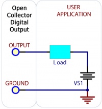
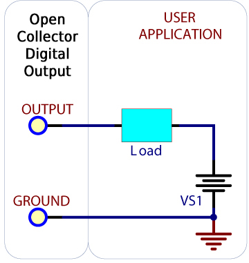
Connect your circuit in series with the digital output, as pictured. The load could be a larger relay, a solenoid, LEDs, light bulbs, motors, etc. Check the specification table on the product page for your Phidget to ensure that the voltage required by your load does not exceed the maximum.
Switching a Relay Board
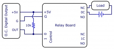
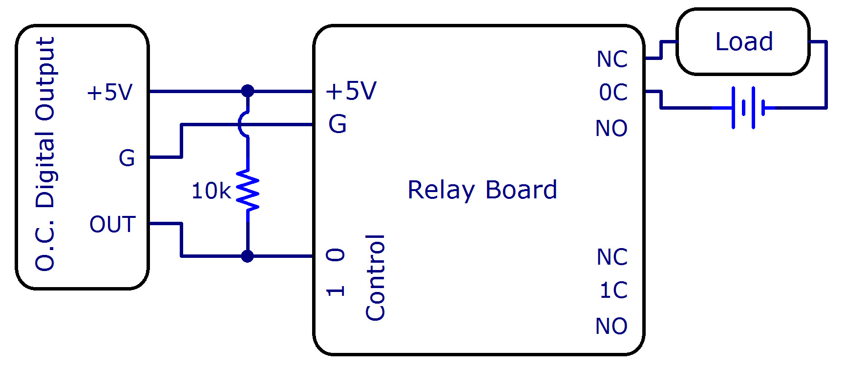
Even though an open collector digital output can be used like a relay by itself, some applications might require a relay board to be switched by the open collector digital outputs. To do this, connect an open collector digital output to the control terminal of the relay board, with a 10kΩ resistor pulling the line up to +5V. This way, the relay will be constantly powered until the open collector digital output is switched on, which will then cause the control line to become grounded. Since this is the opposite of the usual operation of a relay board, you'll have to hook your load up to the normally closed terminal if you want the load to be powered when the digital output is turned on, or connect it to the normally open terminal if you want the load to turn off when the digital output is turned on.
Ground Protection
Ground terminals on some relay boards share a common ground with USB ground. Because they are not internally isolated, these terminals will expose the USB ground potential of the PC to which they are connected. Be sure you are completely familiar with any circuit you intend to connect to a relay board before it is connected. If a reverse voltage or dangerously high potential is applied to the input or output terminals, damage to the Phidget or the computer may result. Limit input and output voltages to the maximum specified on your Phidget's specification table, and always observe correct polarity.