OUT1100 User Guide: Difference between revisions
No edit summary |
|||
| Line 34: | Line 34: | ||
The digital outputs on the OUT1100 are slightly different than the digital outputs on [[InterfaceKit Digital Outputs|Phidget InterfaceKit]] boards. | The digital outputs on the OUT1100 are slightly different than the digital outputs on [[InterfaceKit Digital Outputs|Phidget InterfaceKit]] boards. | ||
===Usage Examples=== | |||
Here are a few things you can do with the OUT1100 Digital Output Phidget | |||
====Drive LEDs==== | |||
[[Image:OUT1100_LED_Diagram.jpg|link=|350px|right]] | |||
To drive an LED with the OUT1100, simply attach the anode to one of the digital output terminals, and the cathode to the the corresponding ground terminal. The built-in series resistance will limit the current and keep the LED from burning out. | |||
====Drive SSRs==== | |||
[[Image:OUT1100_SSR_Diagram.jpg|link=|350px|right]] | |||
To control an SSR with the OUT1100, attach the positive (+) terminal to the output terminal, and the ground (-) terminal to the corresponding ground terminal on the OUT1100. | |||
====Control Relays with Transistors==== | |||
[[Image:OUT1100_Relay_Diagram.jpg|link=|350px|right]] | |||
An inexpensive mosfet and flyback diode circuit can be used to control larger loads (such as relays) from the OUT1100. Be sure to use a Logic-Level MOSFET so that the +5V Digital Output is able to turn it on. Similarly, an NPN transistor could be used in place of the MOSFET, in cases where they may be easier to obtain. | |||
====Isolation with Optocouplers==== | |||
[[Image:OUT1100_Optocoupler_Diagram.jpg|link=|350px|right]] | |||
In some applications, particularly where there is a lot of electrical noise (automotive), or where you want maximum protection of the circuitry (interactive installations, kiosks), electrical isolation buys you a huge margin of protection. Driving the LED causes the output transistor to sink current. | |||
The maximum current through the transistor will depend in part on the characteristics of the optocoupler. | |||
Note that in cases where many isolated outputs are required, you may want to consider using the [[OUT1300]] or [[OUT1301]], which are ready-made isolated digital output Phidgets. | |||
<br clear="all"> | <br clear="all"> | ||
{{UGnext|}} | {{UGnext|}} | ||
Revision as of 17:24, 19 June 2017
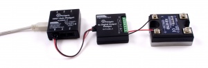
Required Hardware
- An OUT1100 4x Digital Output Phidget
- A VINT Hub
- A USB cable
- A 3-wire Phidget cable
- A computer
- An LED or small electronic device
Connecting the Pieces
- Connect the OUT1100 to the VINT Hub using the Phidget cable.
- Connect the VINT Hub to your computer with a USB cable.
- Connect the positive end of an LED or small device that runs off of 5V to one of the digital outputs, and the negative end to the ground terminal.
Testing Using Windows
Phidget Control Panel
In order to demonstrate the functionality of the OUT1100, the Phidget Control Panel running on a Windows machine will be used.
The Phidget Control Panel is available for use on both macOS and Windows machines.
Windows
To open the Phidget Control Panel on Windows, find the ![]() icon in the taskbar. If it is not there, open up the start menu and search for Phidget Control Panel
icon in the taskbar. If it is not there, open up the start menu and search for Phidget Control Panel
macOS
To open the Phidget Control Panel on macOS, open Finder and navigate to the Phidget Control Panel in the Applications list. Double click on the ![]() icon to bring up the Phidget Control Panel.
icon to bring up the Phidget Control Panel.
For more information, take a look at the getting started guide for your operating system:
Linux users can follow the getting started with Linux guide and continue reading here for more information about the OUT1100.
First Look
After plugging the OUT1100 into your computer and opening the Phidget Control Panel, you will see something like this:
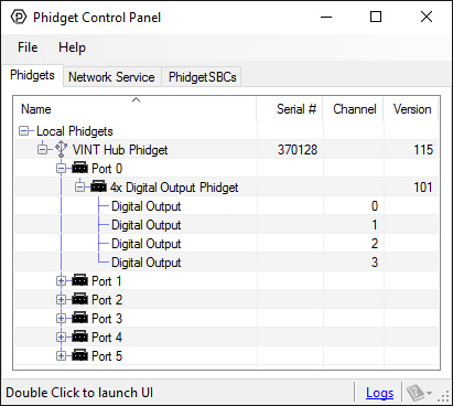
The Phidget Control Panel will list all connected Phidgets and associated objects, as well as the following information:
- Serial number: allows you to differentiate between similar Phidgets.
- Channel: allows you to differentiate between similar objects on a Phidget.
- Version number: corresponds to the firmware version your Phidget is running. If your Phidget is listed in red, your firmware is out of date. Update the firmware by double-clicking the entry.
The Phidget Control Panel can also be used to test your device. Double-clicking on an object will open an example.
Digital Output
Double-click on a Digital Output object {{{2}}} in order to run the example:
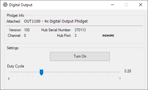
General information about the selected object will be displayed at the top of the window. You can also experiment with the following functionality:
- Toggle the state of the digital output by pressing the button.
Testing Using Mac OS X
- Go to the Quick Downloads section on the Mac OS X page.
- Download and run the Phidget OS X Installer
- Click on System Preferences >> Phidgets (under Other) to activate the Preference Pane
- Make sure your device is properly attached
- Double click on your device's objects in the listing to open them. The Preference Pane and examples will function very similarly to the ones described above in the Windows section.
Testing Using Linux
For a general step-by-step guide on getting Phidgets running on Linux, see the Linux page.
Using a Remote OS
We recommend testing your Phidget on a desktop OS before moving on to remote OS. Once you've tested your Phidget, you can go to the PhidgetSBC, or iOS pages to learn how to proceed.
Technical Details
Output Circuitry
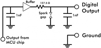
The digital outputs on the OUT1100 are slightly different than the digital outputs on Phidget InterfaceKit boards.
Usage Examples
Here are a few things you can do with the OUT1100 Digital Output Phidget
Drive LEDs
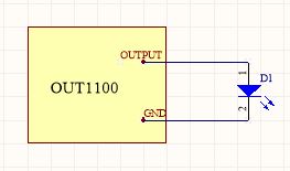
To drive an LED with the OUT1100, simply attach the anode to one of the digital output terminals, and the cathode to the the corresponding ground terminal. The built-in series resistance will limit the current and keep the LED from burning out.
Drive SSRs
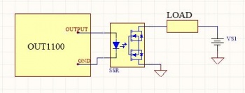
To control an SSR with the OUT1100, attach the positive (+) terminal to the output terminal, and the ground (-) terminal to the corresponding ground terminal on the OUT1100.
Control Relays with Transistors
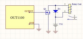
An inexpensive mosfet and flyback diode circuit can be used to control larger loads (such as relays) from the OUT1100. Be sure to use a Logic-Level MOSFET so that the +5V Digital Output is able to turn it on. Similarly, an NPN transistor could be used in place of the MOSFET, in cases where they may be easier to obtain.
Isolation with Optocouplers
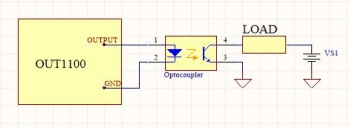
In some applications, particularly where there is a lot of electrical noise (automotive), or where you want maximum protection of the circuitry (interactive installations, kiosks), electrical isolation buys you a huge margin of protection. Driving the LED causes the output transistor to sink current.
The maximum current through the transistor will depend in part on the characteristics of the optocoupler.
Note that in cases where many isolated outputs are required, you may want to consider using the OUT1300 or OUT1301, which are ready-made isolated digital output Phidgets.
What to do Next
- Programming Languages - Find your preferred programming language here and learn how to write your own code with Phidgets!
- Phidget Programming Basics - Once you have set up Phidgets to work with your programming environment, we recommend you read our page on to learn the fundamentals of programming with Phidgets.