OUT1001 User Guide: Difference between revisions
No edit summary |
No edit summary |
||
| Line 26: | Line 26: | ||
===About=== | ===About=== | ||
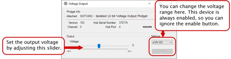
The OUT1001 can provide a DC voltage between -10V and +10V on the 10V terminal. The 5V terminal provides a voltage between 0V to 5V. This Phidget is ideal for analog voltage-controlled devices. | The OUT1001 can provide a DC voltage between -10V and +10V on the 10V terminal. The 5V terminal provides a voltage between 0V to 5V. This Phidget is ideal for analog voltage-controlled devices. | ||
[[Image:OUT1001_About.jpg|link=|center]] | |||
'''Note:''' The 10V terminal has a resolution of 4.9 mV DC. The 5V terminal has a resolution of 1.2 mV DC. | '''Note:''' The 10V terminal has a resolution of 4.9 mV DC. The 5V terminal has a resolution of 1.2 mV DC. | ||
Revision as of 21:26, 11 September 2020
Part 1: Setup
Welcome to the OUT1001 user guide! In order to get started, make sure you have the following hardware on hand:
- OUT1001 - Isolated 12-bit Voltage Output Phidget
- VINT Hub
- Phidget cable
- USB cable and computer
- something to use with the OUT1001 (e.g. multimeter, oscilloscope, device with voltage input, etc.)
Next, you will need to connect the pieces:
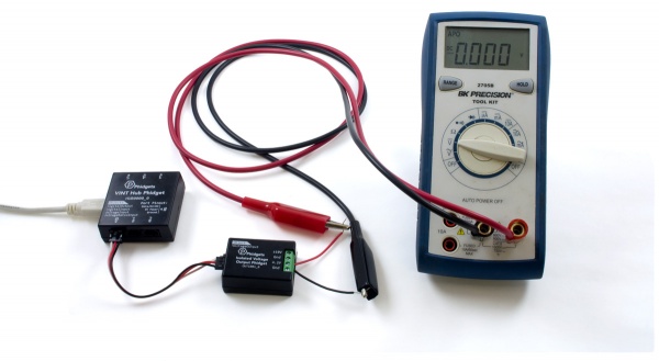
- Connect the OUT1001 to the VINT Hub using the Phidget cable.
- Connect the VINT Hub to your computer with a USB cable.
Now that you have everything together, let's start using the OUT1001!
Phidget Control Panel
In order to demonstrate the functionality of the OUT1001, the Phidget Control Panel running on a Windows machine will be used.
The Phidget Control Panel is available for use on both macOS and Windows machines.
Windows
To open the Phidget Control Panel on Windows, find the ![]() icon in the taskbar. If it is not there, open up the start menu and search for Phidget Control Panel
icon in the taskbar. If it is not there, open up the start menu and search for Phidget Control Panel
macOS
To open the Phidget Control Panel on macOS, open Finder and navigate to the Phidget Control Panel in the Applications list. Double click on the ![]() icon to bring up the Phidget Control Panel.
icon to bring up the Phidget Control Panel.
For more information, take a look at the getting started guide for your operating system:
Linux users can follow the getting started with Linux guide and continue reading here for more information about the OUT1001.
First Look
After plugging the OUT1001 into your computer and opening the Phidget Control Panel, you will see something like this:
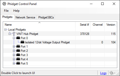
The Phidget Control Panel will list all connected Phidgets and associated objects, as well as the following information:
- Serial number: allows you to differentiate between similar Phidgets.
- Channel: allows you to differentiate between similar objects on a Phidget.
- Version number: corresponds to the firmware version your Phidget is running. If your Phidget is listed in red, your firmware is out of date. Update the firmware by double-clicking the entry.
The Phidget Control Panel can also be used to test your device. Double-clicking on an object will open an example.
Part 2: Using Your Phidget
About
The OUT1001 can provide a DC voltage between -10V and +10V on the 10V terminal. The 5V terminal provides a voltage between 0V to 5V. This Phidget is ideal for analog voltage-controlled devices.

Note: The 10V terminal has a resolution of 4.9 mV DC. The 5V terminal has a resolution of 1.2 mV DC.
Explore Your Phidget Channels Using the Control Panel
You can use your Control Panel to explore your Phidget's channels.
1. Open your Control Panel, and you will find the Isolated 12-bit Volage Output Phidget channel:
2. Double click on the channel to open an example program. This channel belongs to the Voltage Output channel class:
In your Control Panel, double click on "Isolated 12-bit Volage Output Phidget":
Part 3: Create your Program
1. Setting up your Programming Environment
Part 4: Advanced Topics and Troubleshooting
Before you open a Phidget channel in your program, you can set these properties to specify which channel to open. You can find this information through the Control Panel.
1. Open the Control Panel and double-click on the red map pin icon:

2. The Addressing Information window will open. Here you will find all the information you need to address your Phidget in your program.

See the Phidget22 API for your language to determine exact syntax for each property.
The OUT1001 should be subjected to a minimal current draw to ensure maximum voltage precision across the device's full range (less than 5mA in ±10V mode). 5V mode should only be used to set a voltage in high-impedance applications.
However, in the event you plan to power a small load with this device, the OUT1001 will either be sourcing or sinking current when in use.
The device will be a sourcing current when the device is connected to a circuit with a lower voltage potential than its voltage setting. In this situation, the current will be flowing out from the OUT1001 into the circuit.
The device will be a sinking current when the device is connected to a circuit with a higher voltage potential than its voltage setting. In this situation, the current will flow from the circuit into the OUT1001.
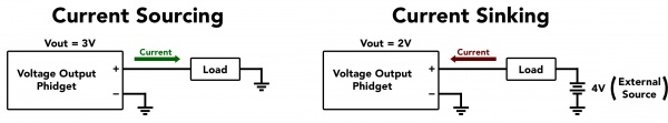
The OUT1001 can source or sink up to 18mA of current depending on the selected output voltage and mode. The chart below shows the maximum available voltage for a given expected current draw.
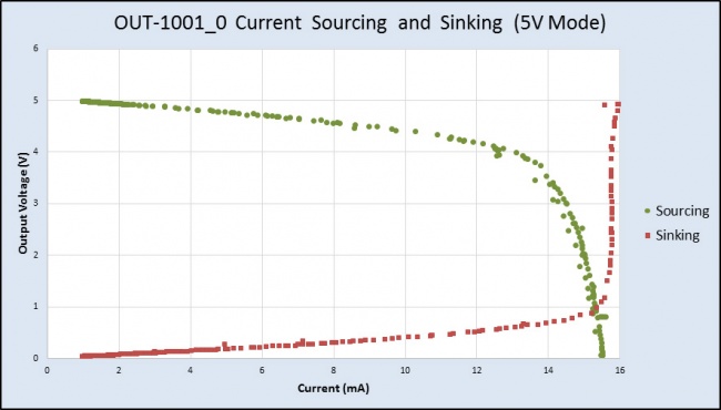
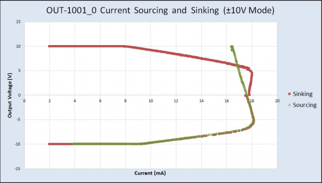
For example, if the connected circuit is pulling 13mA of current, the OUT1001 will only be able to provide a maximum of 4V (in 0-5V mode), even if you try to set it to a higher value.
The OUT1001 may have an unpredictable output voltage for a very short time immediately after the device changes modes or is turned on. If this is a problem in your application, and you have no way to ignore it via software, we recommend using a solid-state relay to switch the output on once it has stabilized.