Motor Selection Guide
Choosing a motor that is suited to the task at hand is one of the most important parts of planning a robotics project. The intent of this guide is to help you decide what sort of motor is needed to accomplish the goals of your project.
Choosing a Motor
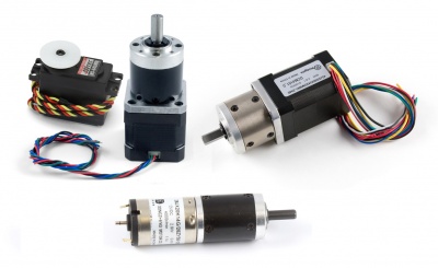
There are 3 categories of electric motors that are used in practical applications and are easily available for purchase. They are:
Each of these classes has several variants and each have their advantages and disadvantages.
Position and Accuracy
The first thing to ask yourself is how precisely the position of the motor must be known. Some applications require nothing more than simple on-off and basic speed control, such as a fan or the powertrain of a vehicle. DC motors are well suited to these sort of applications because they have good speed, torque and are very simple and inexpensive to control.
Other applications have need of very precise movements and angles like robotic arms and model plane control surfaces. Stepper motors and servo motors are best suited to these sort of applications. Servo motors have internal position regulation and are geared down to lower speeds, resulting in very precise position control. Stepper motors move step by step, using magnetic fields to move the motor in discrete increments. Depending on the step size of the motor and the step pattern of the controller stepper motors can achieve extremely accurate position. Often stepper motors have step angles as low as 1.8° and with micro-stepping controllers can be advanced one sixteenth of a step at a time. Through the use of a gearbox even greater accuracy can be achieved since the gearbox has the effect of reducing position increment well below a sixteenth of a step (note that it does not actually change the way the controller steps, it just changes the rotation on the output shaft per 16th step applied). Stepper motors also have the advantage of high holding torque- when the motor is stopped but still powered, it will hold its position firmly.
In general, servo motors are smaller in size and have less torque than a stepper motor. Most servos also have limited range of motion. A typical servo motor has a rotation range of 180° or less, although there are some that are capable of multiple revolutions or even continuous rotation. Servos are most common in RC (remote control) applications where it is not necessary to have high torque or a large range of motion. Stepper motors, on the other hand, are used in applications where extreme precision or high torque is required. CNC (computer numerical control) machines are a prime example of what stepper motors are used for.
Gearboxes
Gearboxes, a common feature of electric motors, use the mechanical advantage of gears to reduce the speed of the motor and increase the torque. By reducing the speed, you also increase the positional accuracy of the motor. The speed and accuracy are affected directly by the gear ratio, as seen in these equations:


For example, a motor with a speed of 500 rpm and a gearbox with a 10:1 gear ratio would result in and output speed of 50 rpm. Likewise, a stepper motor with a step angle of 1.8° with the same gearbox would have a step angle of 0.18°.
Although the reduction ratio plays a large part in determining the Gearbox Output Torque, there is also an inefficiency that is introduced through the use of a gearbox. Some of the torque of the motor is converted into heat and lost due to friction between the gears. Gearbox efficiency depends on the physical characteristics of the gears, the number of gear stages, and gearing system used. You can calculate the Gearbox Output Torque with the following equation:

Keep in mind that while adding a gearbox does increase the torque, the gearbox itself is only rated to withstand a certain amount of torque before it risks becoming damaged or breaking. When selecting a motor, you should always consider the actual operating torque to be the minimum of the output torque and the gearbox strength. For example, a motor that can normally output 5 kg·cm of torque with a 10:1, 90% efficient gearbox whose gears are rated for 40 kg·cm would theoretically be able to output 45 kg·cm of torque, but in practice the 40 kg·cm limit of the gearbox should be considered the maximum torque.
With gearboxes, torque and speed can be seen as one interchangeable characteristic: If you need more torque and less speed, try to find the same motor with a gearbox with a higher reduction ratio. If you need more speed and less torque, try to find the same motor with a gearbox with a lower reduction ratio. However, it is not advisable buy gearboxes and motors separately to mix and match, unless they are specifically designed for each other. There's a lot that can go wrong in gearbox customization and for most users it's a lot less hassle to simply buy a motor with a gearbox already attached.
Encoders
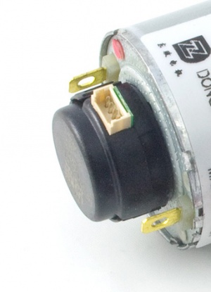
An encoder is a device installed on the shaft of a motor that can be used to keep track of the position of the motor or calculate the speed of the motor. Encoders are often used with a DC motor and a PID control system in order to achieve position/velocity control of a motor that would otherwise only have simple on/off control. Some motors have the shaft exposed on both sides of the motor, so an encoder can be attached on one end without getting in the way of what the motor is driving.
Encoders are rarely used with BLDC motors or servo motors, since they both already have some form of closed-loop position feedback built-in. Encoders are sometimes used with stepper motors, because position control in a stepper motor is open-loop (the controller has no way of knowing whether the stepper actually made it to the desired position, it only knows how far it has told the stepper to go). Excessive vibration, external forces, or sudden high-torque loads can cause steps to be missed, so an encoder would close the control loop and provide actual feedback in this case.
Estimating Required Torque
It can be difficult to estimate how much torque will be required for a certain application before the project is built, but there are plenty of guidelines and rules-of-thumb online that can give you a good idea.

In the case of a typical wheeled vehicle, we recommend you take the mass of the vehicle and multiply by the radius of the wheels, then divide by four. For example, a 20kg vehicle with wheels of radius 6cm would call for a total goal of 30 kg·cm contributed from all of the motors. This should be more than enough torque to move around on smooth terrain and gentle inclines. If you need to be able to handle rough terrain or sharp inclines, you may want to only divide by a factor of 3 or even 2.