Mechanical Relay Guide
|
|
Introduction
Mechanical relays are designed to turn on or turn off the power supplied to other devices using a simple signal from a digital output. They are similar to Solid State Relays except they are less expensive, but are also less sophisticated and have a shorter lifespan. You can use them to control LEDs, heaters, appliances, and generally powered device as long as the power you're switching falls within the limits of the relay you're using.
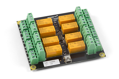
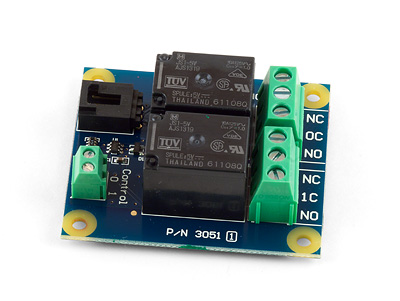
Phidgets sells boards with multiple relays on them, making it easy to control many separate circuits when used with an Interface Kit (or any device with enough Digital Outputs).
How it works

Mechanical relays use a simple electromagnetic coil to open or close the circuit. When current runs through the input and energizes the coil, it creates a small magnetic field which either pulls the arm of the switch away from the other contact of the switch, or pushes it down to close the switch depending on the how the switch is made. A relay also serves as an isolator, because the control (input) and load (output) ends of the relay are not directly connected. This allows you to protect the device you're using to control the relay from power surges in your application.
Basic Use
Controlling a mechanical relay is as easy as turning on an LED. Any Phidgets device with a Digital Output will be able to control a mechanical relay. Relays are often used in large quantities to turn multiple devices on and off in a particular order or timing. For example, a popular trend has been to hook up many strands of Christmas lights to multiple relays and a control system in order to make them flash in rhythm with specific music.
Relays are designed to be controlled by a particular voltage applied to the coil. If you buy a relay product from Phidgets with integrated electronics, this is taken care of for you. If you are integrating your own relay, you'll want to keep an eye on the specifications. The relay coil is also specified for a particular current. For example, a 5V relay might require 70mA. If you connect this relay to a very weak source of 5V, like a digital output, the output will not be able to provide 70mA, and there will not be enough current to switch the relay.
The load side of the relay also requires a minimum current. This minimum load current exists because the electricity needs to conduct through an oxide layer that has formed on the contacts of the relay. If the minimum load current is too high, you won't be able to use your relay to switch a signal, you'll only be able to switch power to a circuit. If you're using a relay to switch a signal, contact bounce might also be a problem.
Switching Speed and High-Frequency Switching
Even though they use moving mechanical parts, mechanical relays switch very quickly. The amount of time it takes for current to begin flowing through the circuit from when the relay's input is activated is in the order of tens of milliseconds. For extremely time-sensitive applications that need to minimize switching delay, Solid State Relays can switch as quickly as 1ms.
You should be careful when using mechanical relays in applications that require very frequent switching. Typically, mechanical relays can only safely manage one contact every few seconds.
Choosing a Relay
Since mechanical relays are nothing more than a controllable switch, they support both AC and DC operation.
The major deciding factor in choosing a mechanical relay is the amount of current it's capable of switching. For example, the most current you can switch with the largest mechanical relay we sell is 5A DC or 10A AC. If the load you're switching consumes more current than a mechanical relay can handle, take a look at our Solid State Relays.
Types or Classes
Switch Type
One of the major characteristics of a mechanical relay is the design of the switch inside.
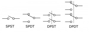
Single Pole, Single Throw (SPST)
This is a simple switch with only one path for the current to follow. The relay is either designed to be normally open or normally closed. If it is normally open, the arm of the switch is held away from the contact with a spring when the relay is off and the electromagnet pulls the arm to make contact and close the switch when the relay is turned on. If it is normally closed, the arm of the switch is held to the contact when the relay is off, and the electromagnet pulls the arm away when the relay is turned on.
Single Pole, Double Throw (SPDT)

This switch has two paths for the current to follow. This type of relay is useful if you want to toggle power between two different loads, as pictured. You can also use a SPDT relay as a single pole, single throw switch, and it can function as normally open or normally closed depending on which pins (common and normally open, or common and normally closed) you connect the load to.
Double Pole, Double Throw (DPDT)
This switch functions the same as a SPDT switch, except there are two of them, but are both controlled by a single input on the relay. You can use this type of switch to simultaneously control two separate circuits.
Troubleshooting
Contact Bounce
As with any mechanical switch, relays are susceptible to contact bounce. This means that when the switch closes, the arm can bounce on the contact, causing the load's power to flicker slightly. This usually only matters when the application is detecting when the power signal turns on. For example, a circuit designed to increment a counter every time power is applied to its input could incorrectly interpret a bouncing switch as multiple events. Check the switch primer for information on how to deal with switch bounce. It's worth noting that Solid State Relays don't suffer from contact bounce, because they operate without using moving mechanical parts.
Arcing, Interference, and Sticking
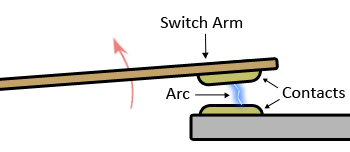
When a mechanical relay opens or closes, and the arm of the switch is very close to the contact, the electric current can arc through the air between the contacts. This arc can cause interference with nearby electrical instruments and sensors.
This arcing can heat up the contacts of the switch enough that they can slowly degrade away until the relay no longer functions. They could also weld together, causing the relay to stay on permanently, which means your load will be powered constantly. If this imposes safety concerns, you should install a fail-safe of some kind. For example, sauna heaters have a simple mechanical thermal shutdown to protect if control electronics fails.
Prolonging Relay Lifespan
In order to prolong the lifespan of your relay, avoid switching loads of higher voltage or current than the relay is built for, and avoid highly inductive loads, which worsen the effects of contact arcing.
Additionally, you should avoid rapid switching if possible. In fact, you can think of a mechanical relay's lifespan in terms of number times switched rather than the amount of time it's used for. A relay that doesn't need to be switched very often can last a long time.
Arc Suppression


The main cause of failure for mechanical relays is electricity arcing across the contacts during switching. To lengthen the lifespan of your relay, you can add various circuit elements that mitigate arcing.
For DC powered applications, one simple method of mitigating the effects of contact arcing is to place a feedback diode across the load, as pictured. This will allow some of the residual electricity in the circuit to recirculate through the load instead of contributing to the arc that forms when the switch makes the transition from closed to open. You can buy a suitable diode from any electronics distributor, like this 10A02 Diode from Digikey.
For AC powered applications, you can put a Metal Oxide Varistor (MOV) across the load terminals of the relay in order to protect it from voltage spikes. An MOV will not remove the entire arc, but it will be helpful in circuits up to several hundred volts.(digikey link)
For low-voltage AC applications, a bi-directional transient voltage suppression diode ("transil diode") that is rated for higher than the AC voltage of the circuit can be placed across the relay terminals in order to protect it from voltage spikes. (digikey link)
Conclusion
Mechanical relays are inexpensive and simple devices that allow AC or DC circuits to be switched on and off using a 0-5V digital signal. They come in a variety of switch formats, enabling the user to build some very clever control into a circuit.
Contact arcing and switch bounce can be an obstacle for some applications, but both are common problems and can be worked around fairly easily. Mechanical relays don't last as long as solid state relays, but if you take care of them, they can be a good cost-effective alternative.
Products in this Category
Glossary
Switch Type
- SPST - either normally open or normally closed. Simple on/off switch.
- SPDT - 3 pins, has both a NO and NC pin and can function like a SPST switch of either type, or can be used to toggle power between two different loads.
- DPDT - Same as SPDT but there are two controlled by the same relay input. Useful for controlling 2 seperate circuits in a synchronized manner.
- Potential selection criteria for specific switching circuits.
Contact Arcing
- As the switch moves from the "on" position to the "off" position (and vice-versa) there is a moment when the arm of the switch in close enough to the contact that electricity will arc through the air, creating lots of heat and possibly damaging the contact. (Diagram would be useful)
- Arcing can lead to sticking, where the switch welds itself closed. If your relay is always on, it might be stuck.
- Arcing will be more severe with higher power loads or highly inductive loads.
- Arcing is expected, but can be mitigated by:
- For DC, feedback diode across load
- For AC, Snubber circuit or
- MOV or
- TVS
Switching Speed
- Lifespan of relay is measured in number of contacts, not time in use. Faster switching -> shorter life.
- Switching is audible - you can hear the switching, which might be annoying / undesirable, or it might be good as a confirmation the system is operating.
- Switching speed is limited by heating in the contacts - the arcing generates heat, and switching high loads faster than the rated switching speed will cause the relay to overheat.
Operating Time
- Time it takes for the arm of the switch to connect with the contact after being activated
- If 10ms is too slow, look at SSRs
Control Voltage
- Can be controlled via digital output
- Relay offers isolation between load circuit and control circuit
Maximum (AC/DC) Switching Voltage
- Secondary selection criteria.
Maximum (AC/DC) Switching Current
- Main selection criteria.
- If they need to switch more than 5A DC, or 10A AC, go to SSRs
- Inductive loads- does the same multiplier apply as for SSRs?
Minimum Switching Current
- A certain amount of current is needed on the LOAD side of a relay.
- Oxide films build up on the contacts, so this minimum is required to conduct through them.
- This spec determines whether or not the relay can switch a signal instead of power.
- If you are switching a signal rather than power, contact bounce could be a problem.