Load Cell Guide
Introduction
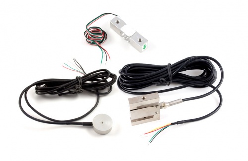
A load cell is a force sensing module - a carefully designed metal structure, with small elements called strain gauges mounted in precise locations on the structure. Load cells are designed to measure a specific force, and ignore other forces being applied. The electrical signal output by the load cell is very small and requires specialized amplification. Fortunately, the DAQ1500 - Wheatstone Bridge Phidget will perform all the amplification and measurement of the electrical output.Load cells are designed to measure force in one direction.
They will often measure force in other directions, but the sensor sensitivity will be different, since parts of the load cell operating under compression are now in tension, and vice versa.
How they work

Strain-gauge load cells convert the load acting on them into electrical signals. The measuring is done with very small resistor patterns called strain gauges - effectively small, flexible circuit boards. The gauges are bonded onto a beam or structural member that deforms when weight is applied, in turn deforming the strain-gauge. As the strain gauge is deformed, it’s electrical resistance changes in proportion to the load.
The changes to the circuit caused by force is much smaller than the changes caused by variation in temperature. Higher quality load cells cancel out the effects of temperature using two techniques. By matching the expansion rate of the strain gauge to the expansion rate of the metal it’s mounted on, undue strain on the gauges can be avoided as the load cell warms up and cools down. The most important method of temperature compensation involves using multiple strain gauges, which all respond to the change in temperature with the same change in resistance. Some load cell designs use gauges which are never subjected to any force, but only serve to counterbalance the temperature effects on the gauges that measuring force. Most designs use 4 strain gauges, some in compression, some under tension, which maximizes the sensitivity of the load cell, and automatically cancels the effect of temperature.
Other types of load cell exist which have half bridges (2 strain gauges) or quarter bridges but they require additional hardware to operate since you must complete the bridge to get the most accurate readings.
What is a Wheatstone bridge?
A Wheatstone bridge is an electrical circuit used to measure and unknown resistance by balancing 2 legs of a bridge circuit. One leg of which contains the unknown value. Wheatstone bridges are made up of 4 resistors or loads in a square with a voltage meter bridging 2 corners of the square and power/ground connected to the other corners. In the case of a load cell, these resistors are strain gauges.
Installation
Single-Point Load Cells
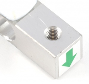
This Single Point Load Cell is used in small jewelry scales and kitchen scales. It’s mounted by bolting down the end of the load cell where the wires are attached, and applying force on the other end in the direction of the arrow. Where the force is applied is not critical, as this load cell measures a shearing effect on the beam, not the bending of the beam. If you mount a small platform on the load cell, as would be done in a small scale, this load cell provides accurate readings regardless of the position of the load on the platform.
Button Load Cells
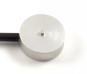
This Button Load Cell is used in applications that require a thin form factor. The bottom of the load cell is bolted, and force applied to the button on the top. By loading only the button, which is slightly rounded, the load cell is less sensitive to errors resulting from the load not pushing down exactly straight on the load cell.
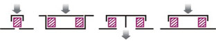
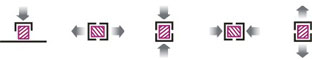
S-Type Load Cells
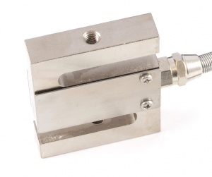
This S-Type load cell can be operated in compression or tension, as illustrated below.
Calibration
You can use this simple formula to convert the measured V/V output from the load cell to the measured force:

Where K is gain value that will change depending on what unit of force or weight you want to measure. Since the offset varies between individual load cells, it’s necessary to measure it for each sensor. Record the output of the load cell at rest on a flat surface with no force on it. The V/V output measured by the Bridge is the offset.
From there we just need to determine the K factor. Take another measurement at some non-zero load (which you know the weight of). Now it's just a matter of solving the above equation for K. From that point forward we can apply the formula to new measured values to determine the force applied.
The K and offset values are something you could then include in your program to perform this calculation automatically.
Multiple Load Cells
For arrays of load cells there are two different configurations you can use:
- The first is to connect each load cell to different channels on your Phidgets. With this setup you would need to calibrate each load cell separately and then you would average the values from all the load cells together.
- The second configuration is to put all the load cells together in parallel on a single channel. This configuration allows you to calibrate all the load cells simultaneously and requires no extra math to work. The downside is that this configuration would not allow you to determine where on the weighing surface an object is resting (which may or may not be important in your application).
Load Cell Specification Glossary
When comparing load cells, there are a number of specifications to consider. This section lists and defines the properties commonly listed on load cells.
Capacity
The maximum load the load cell is designed to measure within its specifications.
Creep
The change in sensor output occurring over 30 minutes, while under load at or near capacity and with all environmental conditions and other variables remaining constant.
Full Scale or FS
Used to qualify error - FULL SCALE is the change in output when the sensor is fully loaded. If a particular error (for example, Non-Linearity) is expressed as 0.1% F.S., and the sensor's maximum range is 0.1V/V, the maximum non-linearity that will be seen over the operating range of the sensor will be 0.0001V/V. An important distinction is that this error doesn’t have to only occur at the maximum load. If you are operating the sensor at a maximum of 10% of capacity, for this example, the non-linearity would still be 0.0001V/V, or 1% of the operating range that you are actually using.
Hysteresis
If a force equal to 50% of capacity is applied to a load cell which has been at no load, a given output will be measured. The same load cell is at full capacity, and some of the force is removed, resulting in the load cell operating at 50% capacity. The difference in output between the two test scenarios is called hysteresis.
Excitation Voltage
Specifies the voltage that can be applied to the power/ground terminals on the load cell. In practice, if you are using the load cell with a Phidget, you don’t have to worry about this spec.
Input Impedance
Determines the power that will be consumed by the load cell. The lower this number is, the more current will be required, and the more heating will occur when the load cell is powered. In very noisy environments, a lower input impedance will reduce the effect of Electromagnetic interference on long wires between the load cell and Phidget.
Insulation Resistance
The electrical resistance measured between the metal structure of the load cell, and the wiring. The practical result of this is the metal structure of the load cells should not be energized with a voltage, particularly higher voltages, as it can arc into the Phidget. Commonly the load cell and the metal framework it is part of will be grounded to earth or to your system ground.
Maximum Overload
The maximum load which can be applied without producing a structural failure.
Non-Linearity
Ideally, the output of the sensor will be perfectly linear, and a simple 2-point calibration will exactly describe the behaviour of the sensor at other loads. In practice, the sensor is not perfect, and Non-linearity describes the maximum deviation from the linear curve. Theoretically, if a more complex calibration is used, some of the non-linearity can be calibrated out, but this will require a very high accuracy calibration with multiple points.
Non-Repeatability
The maximum difference the sensor will report when exactly the same weight is applied, at the same temperature, over multiple test runs.
Operating Temperature
The extremes of ambient temperature within which the load cell will operate without permanent adverse change to any of its performance characteristics.
Output Impedance
Roughly corresponds to the input impedance. If the Output Impedance is very high, measuring the bridge will distort the results. The Phidget carefully buffers the signals coming from the load cell, so in practice this is not a concern.
Rated Output
Is the difference in the output of the sensor between when it is fully loaded to its rated capacity, and when it’s unloaded. Effectively, it’s how sensitive the sensor is, and corresponds to the gain calculated when calibrating the sensor. More expensive sensors have an exact rated output based on an individual calibration done at the factory.
Resolution
Resolution is somewhat misleading when it comes to load cells. People often ask why we don't specify the resolution for our load cells. The fact of the matter is, resolution isn't really a property of the load cells. Rather, it is based on the equipment you are using to measure from the load cell instead. For example, the DAQ1500 has a 24 bit ADC on board. This means that the resolution of a load cell connected to it is 24 bits. Since the excitation voltage for the DAQ1500 is 5V, your expected resolution is:

This is affected by the chosen gain as well. In general, noise means you won't be able to achieve this reliably but the point is that resolution is not a useful spec for a load cell to have.
Safe Overload
The maximum axial load which can be applied without producing a permanent shift in performance characteristics beyond those specified.
Compensated Temperature
The range of temperature over which the load cell is compensated to maintain output and zero balance within specified limits.
Temperature Effect on Span
Span is also called rated output. This value is the change in output due to a 1-degree Celsius change in ambient temperature.
Temperature Effect on Zero
The change in zero balance due to a 1-degree Celsius change in ambient temperature.
Zero Balance
Zero Balance defines the maximum difference between the +/- output wires when no load is applied. Realistically, each sensor will be individually calibrated, at least for the output when no load is applied. Zero Balance is more of a concern if the load cell is being interfaced to an amplification circuit - the Phidget can easily handle enormous differences between +/-. If the difference is very large, the Phidget will not be able to use the higher Gain settings.