Load Cell Guide: Difference between revisions
| (52 intermediate revisions by 5 users not shown) | |||
| Line 1: | Line 1: | ||
[[Category: | {{#seo:|description=What is a load cell? Learn what a load cell is, how they work, and how you can use them with Phidgets.}} | ||
[[Image: | {{#seo:|keywords=load cell}} | ||
[[Category:IntroGuide]] | |||
{{TOC limit|3}} | |||
==Introduction== | |||
Do you need to build a system that can measure weight? Using load cells and load cell interfaces from Phidgets Inc. makes this extremely simple! Watch the video below, or keep reading for more information. | |||
<br><br> | |||
<center>{{#ev:youtube|jCoPfQKMksg|||||rel=0}}</center> | |||
<br><br><br> | |||
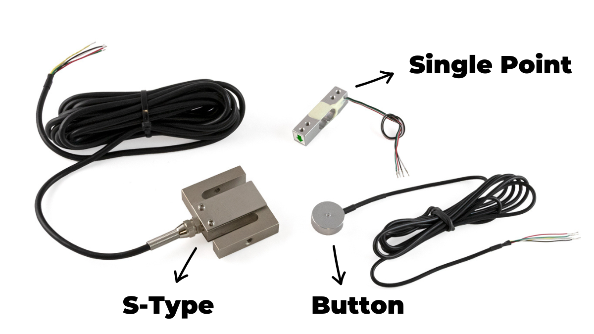
[[Image:Strain_gauge_load_cells2.png|400px|link=https://www.phidgets.com/docs/images/5/59/Strain_gauge_load_cells2.png|thumb|<center>Common types of strain gauge load cells.</center>]] | |||
==What Is a Load Cell?== | |||
A load cell is a device that converts mechanical force into a signal that can be measured. | |||
== | There are different types of load cells, such as pneumatic, hydraulic, capacitive, etc. but '''strain gauge load cells''' are the most common. | ||
<br><br> | |||
===Strain Gauge Load Cells=== | |||
Strain gauge load cells use a small resistive sensor called a ''strain gauge'' to convert mechanical force into an electrical signal. <br><br> | |||
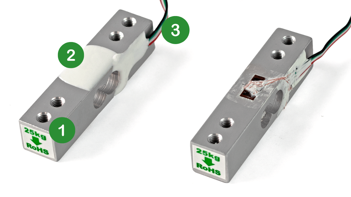
There are many different types of strain gauge load cells (some can be seen in the image above). Each type of load cell is designed for a particular application, however, they all have the same basic components:<br><br> | |||
{| style="margin:auto;width:75%;" class="table-no-border" | |||
| [[Image:1_green.png|25px|link=]] || An inflexible frame or body, generally made of aluminum or a steel alloy. | |||
|- | |||
| [[Image:2_green.png|25px|link=]] || One or more strain gauges. | |||
|- | |||
| [[Image:3_green.png|25px|link=]] || Wires for power, ground, and signals. | |||
|} | |||
<br><br> | |||
[[File:Singlepoint_straingauge_exposed.png|center|500px|link=https://www.phidgets.com/docs/images/a/ac/Singlepoint_straingauge_exposed.png]] | |||
<center>''Strain gauges are typically covered in a protective coating. Here, the coating has been removed from a single-point load cell to expose the strain gauges underneath.''</center> | |||
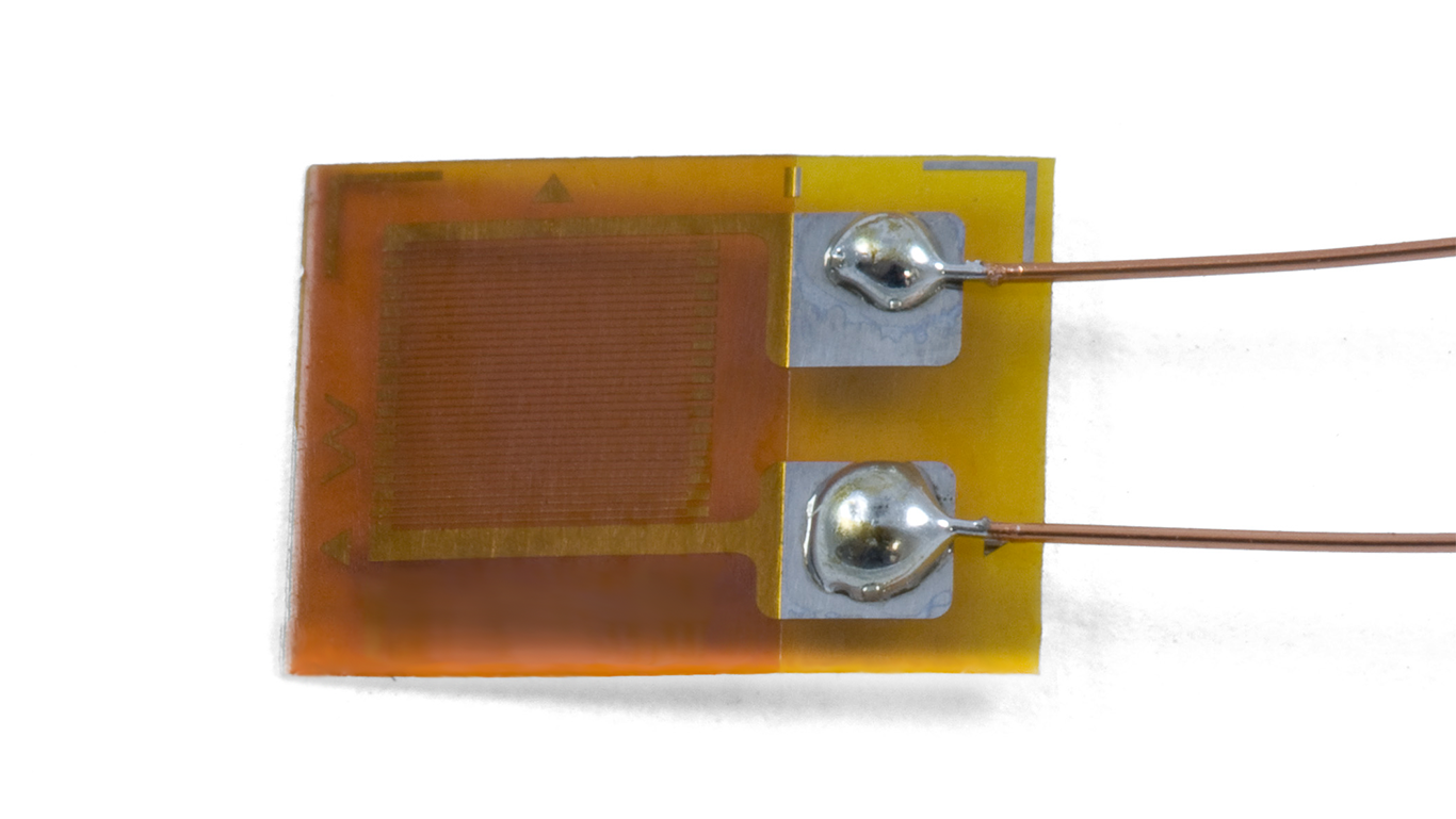
== | ====Strain Gauge Basics==== | ||
[[ | A strain gauge consists of a thin metal wire that is arranged in a specific pattern and attached to a flexible, non-conductive backing material. | ||
[[File:Strain_gauge_single.png|link=https://www.phidgets.com/docs/images/c/c5/Strain_gauge_single.png|center|500px]] | |||
<center>''A strain gauge.''</center> | |||
As the strain gauge experiences tensile or compressive forces, the metal wire deforms which causes the resistance of the strain gauge to change. This change in resistance causes a voltage change which can be measured. | |||
== | ==Which Load Cell Should I Use?== | ||
< | <center>{{#ev:youtube|Wsk8ONCqhaY|||||rel=0}}</center> | ||
There are many different types of strain gauge load cells to choose from. Phidgets Inc. carries the following types and capacities: | |||
{| style="margin:auto;width:85%;" | |||
|- | |||
! Type !! Description !! Max Capacity !! | |||
|- | |||
| [[#Single-Point Load Cells|Single-Point]] || Used for small to medium-capacity weighing scales (e.g. kitchen scale). || 50kg || [[File:Singlepoint_illustration.png|200px|link=]] | |||
|- | |||
| [[#S-Type Load Cells|S-Type]] || Used to measure tension (e.g. hanging loads), and, less commonly, compressive forces. || 500kg || [[File:Stype_illustration.png|200px|link=]] | |||
|- | |||
| [[#Platform Load Cells|Platform]] || Used for robust multi-point weighing platforms.|| 500kg +||[[File:Shear_illustration.png|200px|link=]][[File:Platform_illustration.png|200px|link=]] | |||
|- | |||
| [[#Button Load Cells|Button]] || Used for weighing scales, especially where space is limited. || 1000kg ||[[File:Button_illustration.png|200px|link=]] | |||
|} | |||
===Single-Point Load Cells=== | |||
Single-point load cells, sometimes referred to as ''Platform'' or ''Binocular'' load cells, are easy-to-use load cells that are commonly seen in small weighing scales (e.g. kitchen scales). | |||
====Form Factor==== | |||
[[File:Measurement_axis.png|thumb|link=https://www.phidgets.com/docs/images/9/9a/Measurement_axis.png|<center>A single-point load cell with a capacity of 780g</center>]] | |||
These load cells are beam shaped and typically have two circular holes machined out of the middle (hence, 'binocular load cells'). These holes encourage bending along the measurement axis. They also have mounting holes (generally 1-2) at both ends for simple installation. | |||
[ | ====Use Cases==== | ||
Single point load cells are primarily used to create platform scales, like the [https://www.phidgets.com/?tier=3&catid=9&pcid=7&prodid=1196 Weighing Scale Kit]. They are ideal for this task because they support off-axis loading. This means that users can place their object anywhere on the surface of the scale and the results will still be accurate. | |||
< | ====Installation==== | ||
Single-point load cells typically have an arrow showing which direction the load should be applied. One end of the load cell is secured to the base of the platform, while the other is secured to the top plate. These load cells cannot be combined to increase weighing capacity. | |||
[[File:Singlepoint_scale_installed.jpg|center|600px|link=https://www.phidgets.com/docs/images/8/81/Singlepoint_scale_installed.jpg]] | |||
<center>''A 5kg single-point load cell installed in a small weighing platform.''</center> | |||
===S-Type Load Cells=== | ===S-Type Load Cells=== | ||
S-type load cells, sometimes referred to as ''Z-type'' or ''S-beam'' load cells, are easy-to-use load cells that allow you to measure both tensile and compressive forces. | |||
[[File: | ====Form Factor==== | ||
[[File:S type mounting.jpg|thumb|link=https://www.phidgets.com/docs/images/2/26/S_type_mounting.jpg|<center>A S-Type load cell with a capacity of 500kg</center>]] | |||
These load cells are S-shaped, with two mounting holes located at the top and bottom. | |||
====Use Cases==== | |||
S-type load cells are primarily used to measure the weight of suspended loads, the strength/durability of wires, cables, ropes, etc., and any other tensile application. They can also be used in compression, though it is less common. | |||
====Installation==== | |||
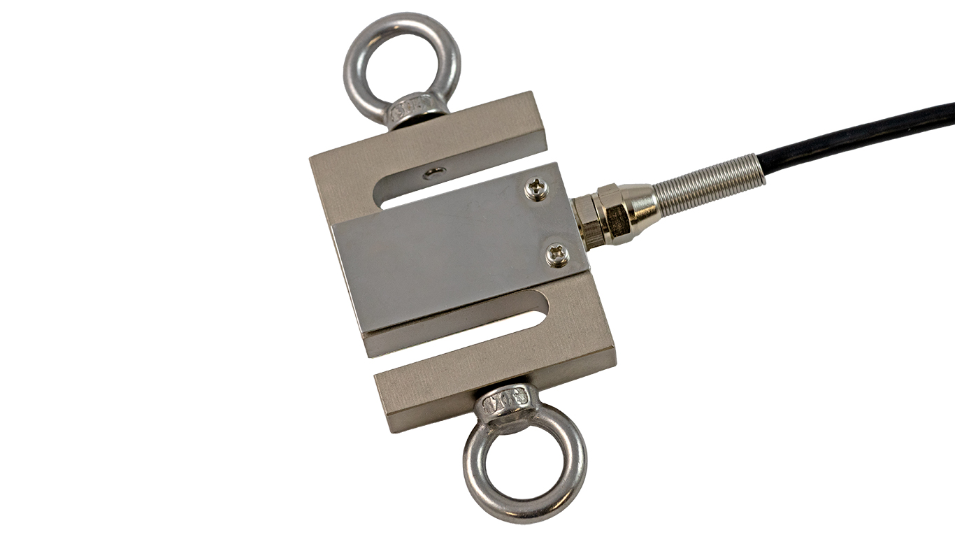
S-type load cells are generally used with eye bolts or rod end bearings which provide an easy connection point to the rest of a system. | |||
[[File: | [[File:S_type_eye_bolt.jpg|center|500px|link=https://www.phidgets.com/docs/images/6/66/S_type_eye_bolt.jpg]] | ||
< | <center>''A 100kg S-Type load cell with eye bolts attached. ''</center> | ||
== | ===Platform Load Cells=== | ||
Platform load cells are designed to be used in parallel for multipoint load cell platforms. | |||
====Form Factor==== | |||
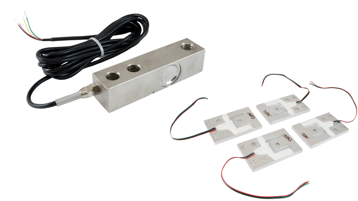
[[File:Platformloadcells.png|thumb|link=https://cdn.phidgets.com/docs/images/a/a3/Platformloadcells.png|<center>A shear beam load cell and platform load cells (matched set of 4)</center>]] | |||
Platform load cells from Phidgets Inc. are currently available in two different form factors: | |||
* Shear beam | |||
* Platform (Matched set of 4) | |||
Shear beam load cells are typically beam-shaped with a solid rectangular profile. Our platform load cells are flat with multiple holes machine out of the body. | |||
====Use Cases==== | |||
Platform load cells are used to create durable multipoint weighing platforms that can easily handle large dynamic loads. Examples are bathroom scales and livestock scales. | |||
====Installation==== | |||
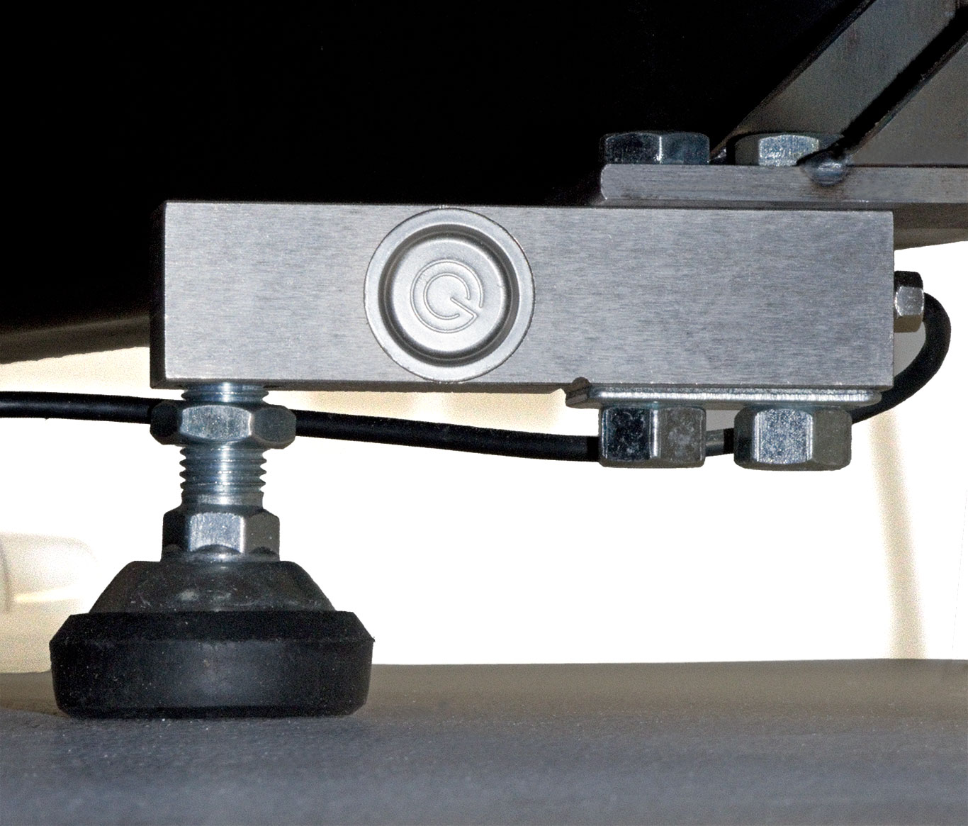
Our shear beam load cells typically have an arrow showing which direction the load should be applied. One end of the load cell is secured to the base of the platform or can be placed directly on the ground using the included rubber swivel foot, while the other is secured to the top plate. | |||
[[Image:Shearbeam_foot_phidgets.jpg|300px|center|link=https://cdn.phidgets.com/docs/images/0/0b/Shearbeam_foot_phidgets.jpg]] | |||
<center>''A shear beam load cell installed using a rubber swivel foot.''</center> | |||
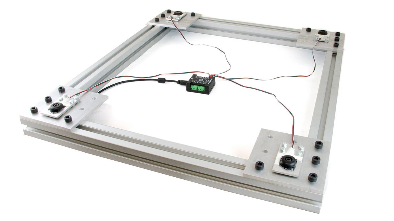
Our platform load cells (matched set of 4) have four mounting holes for easy connection onto a frame, and a single mounting hole that is often used with a rubber pad or vibration mount that rests on the ground. | |||
== | [[File:Platformset_installed.jpg|center|500px|link=https://cdn.phidgets.com/docs/images/3/37/Platformset_installed.jpg]] | ||
<center>''Platform load cells (matched set of 4) installed on a weighing structure and connected to a [https://www.phidgets.com/?prodid=1270 PhidgetBridge 4-Input].''</center> | |||
<br><br> | |||
===Button Load Cells=== | |||
Button load cells, sometimes called ''load buttons'', are low-profile load cells that allow you to measure compressive forces. | |||
====Form Factor==== | |||
[[File:Loadcell_button.gif|thumb|link=https://www.phidgets.com/docs/images/4/4e/Loadcell_button_big.gif|<center>A button load cell with a capacity of 50kg</center>]] | |||
These load cells are small and cylindrical. They have a small button protruding from the top where mechanical force is intended to be focused. They also have mounting holes (generally 3-4) on the bottom. | |||
====Use Cases==== | |||
Button load cells are primarily used for weighing applications where space is limited. Multiple button load cells can be used together to increase weighing capacity. | |||
====Installation==== | |||
The bottom of the load cell can be easily secured to a base using mounting holes. A top plate can be added, though precise cutouts for the protruding buttons are required. | |||
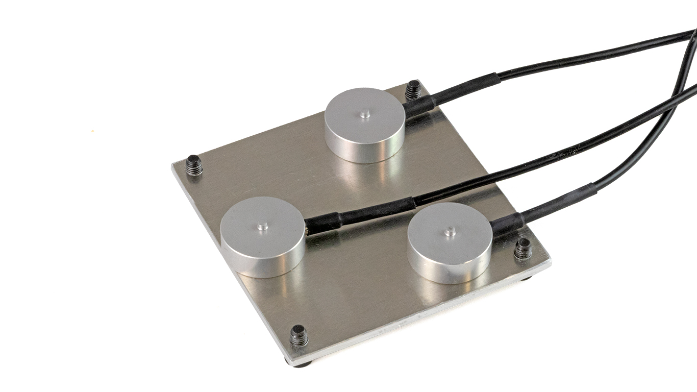
[[File:Button_installed.jpg|center|500px|link=https://www.phidgets.com/docs/images/4/42/Button_installed.jpg]] | |||
<center>''Three 50kg button load cells installed in a weighing platform (top plate not shown).''</center> | |||
<br><br> | |||
===Load Cell Accuracy=== | |||
Load cells sold by Phidgets Inc. are categorized into different types, as mentioned above, as well as different accuracy classes. An overview of general accuracy is available in the table below: | |||
{ | {| style="margin:auto;width:85%;" | ||
|- | |||
! Class !! Total Error | |||
|- | |||
| C4 || 0.020% | |||
|- | |||
| C3 || 0.025% | |||
|- | |||
| C2 || 0.031% | |||
|- | |||
| C1 || 0.053% | |||
|- | |||
| Consumer || 0.1% | |||
|} | |||
As shown above, class C4 load cells have less total error, and provide greater performance regarding accuracy, repeatability, and drift. | |||
==How Do I Get Data From My Load Cell?== | |||
The | The output from a load cell is a very small analog voltage. Amplification is required in order to obtain useful data. Luckily, the load cell interfaces from Phidgets Inc. do this for you and provide a clean, stable digital value to work with. | ||
{{ | ===Selecting a Load Cell Interface=== | ||
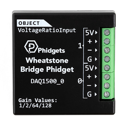
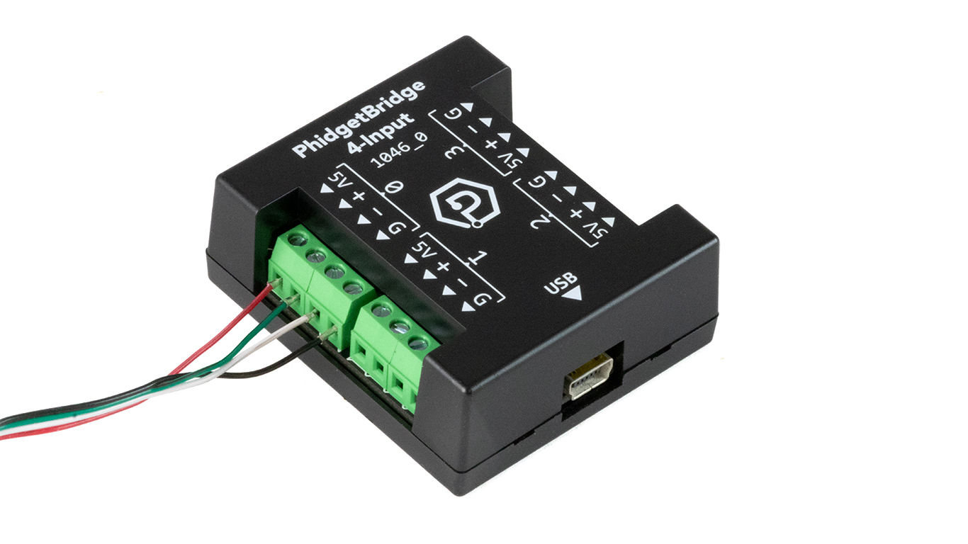
Phidgets Inc. offers two load cell interfaces: | |||
{| style="margin:auto;width:75%;" class="table-no-border" | |||
|- | |||
| [[File:DAQ1500_square.jpg|link=https://www.phidgets.com/docs/images/0/08/DAQ1500_square.jpg|250px]] || [[File:1046_1_square.jpg|link=https://www.phidgets.com/docs/images/b/ba/1046_1_square.png|250px]] | |||
|} | |||
<br><br> | |||
====Relevant Specifications==== | |||
{| style="width: 85%; | |||
|- | |||
! !! [https://www.phidgets.com/?tier=3&catid=64&pcid=57&prodid=957 Wheatstone Bridge Phidget (DAQ1500_0)]!! [https://www.phidgets.com/?tier=3&catid=98&pcid=78&prodid=1270 PhidgetBridge 4-Input (1046_1)] | |||
|- | |||
| Controlled By || VINT || USB | |||
|- | |||
| Load Cell Inputs|| 2 || 4 | |||
|- | |||
| Maximum Sample Rate (One Input Used) || 50Hz || 1200Hz | |||
|- | |||
| Maximum Sample Rate (All Inputs Used)|| 10Hz || 125Hz | |||
|- | |||
| ADC Resolution|| 24 bits - 59.9nV/V || 24 bits - 59.9nV/V | |||
|- | |||
| Avg System Cost || $60USD || $95USD | |||
|} | |||
===Connecting Your Load Cell to Your Load Cell Interface=== | |||
After selecting a load cell interface, you can easily connect your load cell to it using a 2mm screwdriver. | |||
[[File:1046_side_wires.jpg|center|500px|link=https://www.phidgets.com/docs/images/b/b7/1046_side_wires.jpg]] | |||
<center>''Load cell connected to PhidgetBridge 4-Input</center> | |||
<br><br> | |||
Be sure to check the datasheet for your specific load cell before connecting. | |||
{| style="width:75%;" | |||
|- | |||
! Wire Color !! Function !! Load Cell Interface Port | |||
|- | |||
|- | |||
| Red || VCC || 5V | |||
|- | |||
| Green || + || + | |||
|- | |||
| White || - || - | |||
|- | |||
| Black || GND || G | |||
|} | |||
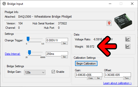
==How Do I Convert My Load Cell Output To Pounds, Grams, Newtons, etc.== | |||
The | The output from a load cell is normally reported with units of volts per volt (V/V) or milliVolt per volt (mV/V). | ||
[[File:Bridge_controlpanel_1_arr.png|500px|center|link=https://www.phidgets.com/docs/images/4/4d/Bridge_controlpanel_1_arr.png]] | |||
<center>''The raw output from a load cell measured using the [https://www.phidgets.com/docs/Phidget_Control_Panel Phidget Control Panel].''</center> | |||
In order to convert the units into something more meaningful like grams, pounds, newtons, etc. a simple calibration is required. For more information, visit our [https://www.phidgets.com/docs/Calibrating_Load_Cells load cell calibration guide]. | |||
[[File:Bridge_controlpanel_2_arr.png|500px|center|link=https://www.phidgets.com/docs/images/0/0e/Bridge_controlpanel_2_arr.png]] | |||
<center>''The calibrated output from a load cell. Here, weight is being measured in grams.''</center> | |||
<br><br> | |||
==Load Cells - Related Topics== | |||
* [https://www.phidgets.com/docs/Calibrating_Load_Cells Calibrating Load Cells] | |||
Latest revision as of 17:29, 7 December 2023
Introduction
Do you need to build a system that can measure weight? Using load cells and load cell interfaces from Phidgets Inc. makes this extremely simple! Watch the video below, or keep reading for more information.
What Is a Load Cell?
A load cell is a device that converts mechanical force into a signal that can be measured.
There are different types of load cells, such as pneumatic, hydraulic, capacitive, etc. but strain gauge load cells are the most common.
Strain Gauge Load Cells
Strain gauge load cells use a small resistive sensor called a strain gauge to convert mechanical force into an electrical signal.
There are many different types of strain gauge load cells (some can be seen in the image above). Each type of load cell is designed for a particular application, however, they all have the same basic components:
| An inflexible frame or body, generally made of aluminum or a steel alloy. | |
| One or more strain gauges. | |
| Wires for power, ground, and signals. |
Strain Gauge Basics
A strain gauge consists of a thin metal wire that is arranged in a specific pattern and attached to a flexible, non-conductive backing material.
As the strain gauge experiences tensile or compressive forces, the metal wire deforms which causes the resistance of the strain gauge to change. This change in resistance causes a voltage change which can be measured.
Which Load Cell Should I Use?
There are many different types of strain gauge load cells to choose from. Phidgets Inc. carries the following types and capacities:
| Type | Description | Max Capacity | |
|---|---|---|---|
| Single-Point | Used for small to medium-capacity weighing scales (e.g. kitchen scale). | 50kg | 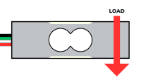
|
| S-Type | Used to measure tension (e.g. hanging loads), and, less commonly, compressive forces. | 500kg | 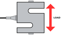
|
| Platform | Used for robust multi-point weighing platforms. | 500kg + | 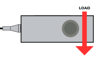 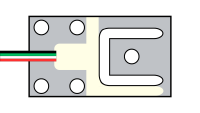
|
| Button | Used for weighing scales, especially where space is limited. | 1000kg | 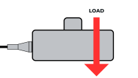
|
Single-Point Load Cells
Single-point load cells, sometimes referred to as Platform or Binocular load cells, are easy-to-use load cells that are commonly seen in small weighing scales (e.g. kitchen scales).
Form Factor
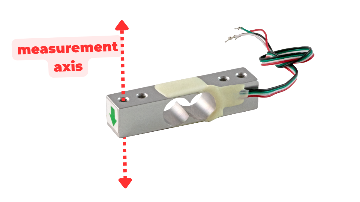
These load cells are beam shaped and typically have two circular holes machined out of the middle (hence, 'binocular load cells'). These holes encourage bending along the measurement axis. They also have mounting holes (generally 1-2) at both ends for simple installation.
Use Cases
Single point load cells are primarily used to create platform scales, like the Weighing Scale Kit. They are ideal for this task because they support off-axis loading. This means that users can place their object anywhere on the surface of the scale and the results will still be accurate.
Installation
Single-point load cells typically have an arrow showing which direction the load should be applied. One end of the load cell is secured to the base of the platform, while the other is secured to the top plate. These load cells cannot be combined to increase weighing capacity.

S-Type Load Cells
S-type load cells, sometimes referred to as Z-type or S-beam load cells, are easy-to-use load cells that allow you to measure both tensile and compressive forces.
Form Factor
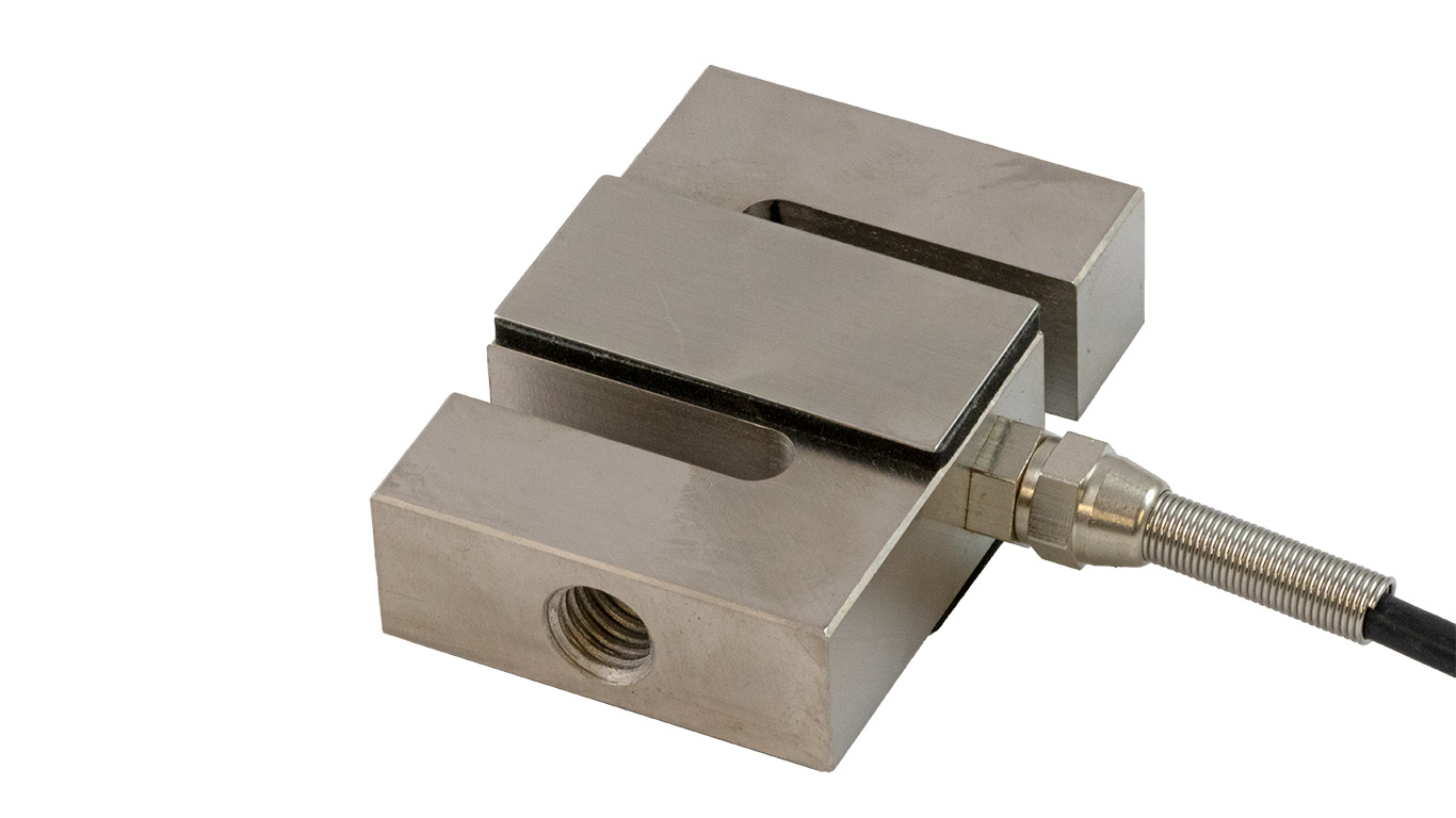
These load cells are S-shaped, with two mounting holes located at the top and bottom.
Use Cases
S-type load cells are primarily used to measure the weight of suspended loads, the strength/durability of wires, cables, ropes, etc., and any other tensile application. They can also be used in compression, though it is less common.
Installation
S-type load cells are generally used with eye bolts or rod end bearings which provide an easy connection point to the rest of a system.
Platform Load Cells
Platform load cells are designed to be used in parallel for multipoint load cell platforms.
Form Factor
Platform load cells from Phidgets Inc. are currently available in two different form factors:
- Shear beam
- Platform (Matched set of 4)
Shear beam load cells are typically beam-shaped with a solid rectangular profile. Our platform load cells are flat with multiple holes machine out of the body.
Use Cases
Platform load cells are used to create durable multipoint weighing platforms that can easily handle large dynamic loads. Examples are bathroom scales and livestock scales.
Installation
Our shear beam load cells typically have an arrow showing which direction the load should be applied. One end of the load cell is secured to the base of the platform or can be placed directly on the ground using the included rubber swivel foot, while the other is secured to the top plate.
Our platform load cells (matched set of 4) have four mounting holes for easy connection onto a frame, and a single mounting hole that is often used with a rubber pad or vibration mount that rests on the ground.
Button Load Cells
Button load cells, sometimes called load buttons, are low-profile load cells that allow you to measure compressive forces.
Form Factor
These load cells are small and cylindrical. They have a small button protruding from the top where mechanical force is intended to be focused. They also have mounting holes (generally 3-4) on the bottom.
Use Cases
Button load cells are primarily used for weighing applications where space is limited. Multiple button load cells can be used together to increase weighing capacity.
Installation
The bottom of the load cell can be easily secured to a base using mounting holes. A top plate can be added, though precise cutouts for the protruding buttons are required.
Load Cell Accuracy
Load cells sold by Phidgets Inc. are categorized into different types, as mentioned above, as well as different accuracy classes. An overview of general accuracy is available in the table below:
| Class | Total Error |
|---|---|
| C4 | 0.020% |
| C3 | 0.025% |
| C2 | 0.031% |
| C1 | 0.053% |
| Consumer | 0.1% |
As shown above, class C4 load cells have less total error, and provide greater performance regarding accuracy, repeatability, and drift.
How Do I Get Data From My Load Cell?
The output from a load cell is a very small analog voltage. Amplification is required in order to obtain useful data. Luckily, the load cell interfaces from Phidgets Inc. do this for you and provide a clean, stable digital value to work with.
Selecting a Load Cell Interface
Phidgets Inc. offers two load cell interfaces:
 |

|
Relevant Specifications
| Wheatstone Bridge Phidget (DAQ1500_0) | PhidgetBridge 4-Input (1046_1) | |
|---|---|---|
| Controlled By | VINT | USB |
| Load Cell Inputs | 2 | 4 |
| Maximum Sample Rate (One Input Used) | 50Hz | 1200Hz |
| Maximum Sample Rate (All Inputs Used) | 10Hz | 125Hz |
| ADC Resolution | 24 bits - 59.9nV/V | 24 bits - 59.9nV/V |
| Avg System Cost | $60USD | $95USD |
Connecting Your Load Cell to Your Load Cell Interface
After selecting a load cell interface, you can easily connect your load cell to it using a 2mm screwdriver.
Be sure to check the datasheet for your specific load cell before connecting.
| Wire Color | Function | Load Cell Interface Port |
|---|---|---|
| Red | VCC | 5V |
| Green | + | + |
| White | - | - |
| Black | GND | G |
How Do I Convert My Load Cell Output To Pounds, Grams, Newtons, etc.
The output from a load cell is normally reported with units of volts per volt (V/V) or milliVolt per volt (mV/V).
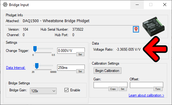
In order to convert the units into something more meaningful like grams, pounds, newtons, etc. a simple calibration is required. For more information, visit our load cell calibration guide.