Digital Input Guide: Difference between revisions
No edit summary |
|||
| (10 intermediate revisions by 2 users not shown) | |||
| Line 1: | Line 1: | ||
<metadesc>Digital Inputs are used to read the state of devices such as buttons or switches. You can find digital input interfaces at Phidgets.com.</metadesc> | |||
[[Category: Primer]] | [[Category: Primer]] | ||
==Introduction== | ==Introduction== | ||
[[File:DAQ1300_0.jpg|link=|right|400px]] | |||
Digital Inputs can be used to convey the state of various devices such as push buttons, limit switches, relays, or logic level outputs. They have two states: high and low. Any signal that is expected to interact with more than just these 2 states is inappropriate for this type of input. | |||
Digital | Digital inputs are one of the easiest components to work with, since all that is required is a simple check to see which state they are in when an event triggers. A digital input can either be ''Active High'' or ''Active Low'': | ||
*'''Active Low''' digital inputs consider their state to be TRUE when the voltage is low (closer to 0V), and FALSE when high (closer to 5V). | |||
*'''Active High''' digital inputs are the opposite- TRUE when the voltage is high, and FALSE when the voltage is low. | |||
The exact voltage values at which a digital input switches varies from device to device. See the specification table for your Phidget for more details. | |||
Below is a table of Phidgets with digital inputs, and their type of digital input: | Below is a table of Phidgets with digital inputs, and their type of digital input: | ||
{|class="wikitable" style="text-align: center; margin:auto;" | |||
{| style=" | |-style="background: #f0f0f0" | ||
|-style="background: #f0f0f0" | |'''Product #''' || '''Name''' || '''Digital Input Type''' | ||
|- | |- | ||
|1010 | |||
| [{{SERVER}}/products.php?product_id=1010 PhidgetInterfaceKit 8/8/8 Mini-Format] | |||
| Active Low | |||
|- | |- | ||
| 1011 | |||
| [{{SERVER}}/products.php?product_id=1011 PhidgetInterfaceKit 2/2/2] | |||
| Active Low | |||
|- | |- | ||
| 1012 | |||
| [{{SERVER}}/products.php?product_id=1012 PhidgetInterfaceKit 0/16/16] | |||
| Active High | |||
|- | |- | ||
| 1018 | |||
| [{{SERVER}}/products.php?product_id=1018 PhidgetInterfaceKit 8/8/8] | |||
| Active Low | |||
|- | |- | ||
| 1019 | |||
| [{{SERVER}}/products.php?product_id=1019 PhidgetInterfaceKit 8/8/8 w/6 Port Hub] | |||
| Active Low | |||
|- | |- | ||
| 1073 | |||
| [{{SERVER}}/products.php?product_id=1073 PhidgetSBC3] | |||
| Active Low | |||
|- | |- | ||
| 1203 | |||
| [{{SERVER}}/products.php?product_id=1203 PhidgetTextLCD] | |||
| Active Low | |||
|- | |- | ||
| DAQ1200 | |||
| [{{SERVER}}/products.php?product_id=DAQ1200 4x Digital Input Phidget] | |||
| Active Low | |||
|- | |- | ||
| DAQ1300 | |||
| [{{SERVER}}/products.php?product_id=DAQ1300 4x Isolated Digital Input Phidget] | |||
| Active High | |||
|- | |- | ||
| DAQ1301 | |||
| [{{SERVER}}/products.php?product_id=DAQ1301 16x Isolated Digital Input Phidget] | |||
| Active High | |||
|- | |- | ||
| HUB0000 | |||
| [{{SERVER}}/products.php?product_id=HUB0000 VINT Hub Phidget] | |||
| Active Low | |||
|} | |} | ||
==Specifications== | ==Specifications== | ||
===Digital Input Hardware Filter=== | ===Digital Input Hardware Filter=== | ||
There is built-in filtering on the digital input, to eliminate false triggering from electrical noise. | There is built-in filtering on the digital input, to eliminate false triggering from electrical noise. | ||
| Line 90: | Line 85: | ||
[[Image:digital_input.jpg|right|300px|link=|thumb|Schematic for a Phidgets digital input.]] | [[Image:digital_input.jpg|right|300px|link=|thumb|Schematic for a Phidgets digital input.]] | ||
The digital inputs have a built in | The digital inputs have a built in pull-up resistor. (It may be a 10 kOhm or 15 kOhm resistor depending on the Phidget). | ||
By connecting external circuitry, and forcing the input to Ground, the Digital Input in software will read as TRUE. | By connecting external circuitry, and forcing the input to Ground, the Digital Input in software will read as TRUE. | ||
The default state is FALSE - when you have nothing connected, or your circuitry (switch, etc) is not pulling the input to ground. | The default state is FALSE - when you have nothing connected, or your circuitry (switch, etc) is not pulling the input to ground. | ||
| Line 103: | Line 98: | ||
[[Image:switch_digital_input.jpg|right|300px|link=|thumb|Schematic for connecting a switch to a digital input.]] | [[Image:switch_digital_input.jpg|right|300px|link=|thumb|Schematic for connecting a switch to a digital input.]] | ||
Closing the switch causes the digital input to | Closing or opening the switch causes the digital input to change state. | ||
<br clear="all"> | <br clear="all"> | ||
===Monitoring the Position of a Relay=== | ===Monitoring the Position of a Relay=== | ||
| Line 111: | Line 107: | ||
The relay contact can be treated as a switch, and wired up similarly. | The relay contact can be treated as a switch, and wired up similarly. | ||
When the relay contact is closed, the Digital Input will | When the relay contact is opened or closed, the Digital Input's state will change. | ||
<br clear="all"> | <br clear="all"> | ||
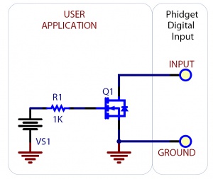
===Detecting an External Voltage with an N-Channel MOSFET=== | ===Detecting an External Voltage with an N-Channel MOSFET=== | ||
| Line 120: | Line 117: | ||
A MOSFET can be used to detect the presence of an external voltage. | A MOSFET can be used to detect the presence of an external voltage. | ||
The external voltage will turn on the MOSFET, causing it to short the Digital Input to Ground. | The external voltage will turn on the MOSFET, causing it to short the Digital Input to Ground. | ||
The voltage level required to turn on the MOSFET depends on the make of of MOSFET you are using. Typical values are 2V-6V. | The voltage level required to turn on the MOSFET depends on the make of of MOSFET you are using. Typical values are 2V-6V. | ||
<br clear="all"> | <br clear="all"> | ||
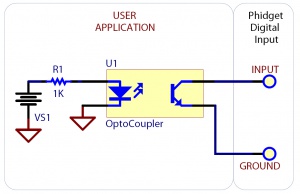
===Isolating a Digital Input with an Optocoupler=== | ===Isolating a Digital Input with an Optocoupler=== | ||
[[Image:isolating_digital_input_optocoupler.jpg|right|300px|link=|thumb|Schematic showing isolation of a digital input with an optocoupler.]] | [[Image:isolating_digital_input_optocoupler.jpg|right|300px|link=|thumb|Schematic showing isolation of a digital input with an optocoupler.]] | ||
You can use an optocoupler to isolate a digital input from the device it's reading, which is useful for avoiding [[Electricity Primer#Shared Grounds|ground loops]] in some systems. | |||
The amount of current required will depend on the optocoupler used. | The amount of current required will depend on the optocoupler used. | ||
<br clear="all"> | <br clear="all"> | ||
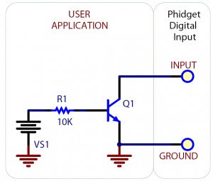
===Detecting an External Voltage with an NPN Transistor=== | ===Detecting an External Voltage with an NPN Transistor=== | ||
| Line 139: | Line 135: | ||
This circuit can be used to measure if a battery is connected, or if 12V (for example) is on a wire. | This circuit can be used to measure if a battery is connected, or if 12V (for example) is on a wire. | ||
<br clear="all"> | <br clear="all"> | ||
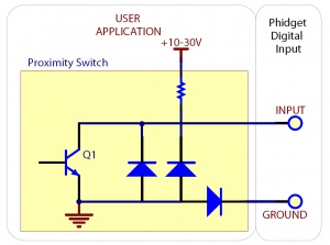
===Using a Capacitive or Inductive Proximity Switch=== | ===Using a Capacitive or Inductive Proximity Switch=== | ||
| Line 151: | Line 147: | ||
Similar capacitive or inductive proximity switches from other manufacturers should work just as well. | Similar capacitive or inductive proximity switches from other manufacturers should work just as well. | ||
{| | {|class="wikitable" style="text-align: center; margin:auto;" | ||
|+'''Switches''' | |+'''Switches''' | ||
|- | |- | ||
|style="background:#f0f0f0;" |'''Manufacturer''' | |||
|style="background:#f0f0f0;" |'''Web Page ''' | |||
|style="background:#f0f0f0;" |'''Capacitive Part No.''' | |||
|style="background:#f0f0f0;" |'''Inductive Part No.''' | |||
|- | |- | ||
| Automation Direct | | Automation Direct | ||
| www.automationdirect.com | | [https://www.automationdirect.com Automated Direct] | ||
| CT1 Series | | CT1 Series | ||
| AM1 Series | | AM1 Series | ||
| Line 171: | Line 167: | ||
The digital inputs can be easily wired to use many variable resistors as switches. | The digital inputs can be easily wired to use many variable resistors as switches. | ||
The digital input will activate either when the FSR is pressed, or when it is not pressed, depending on whether your digital input is active high or active low. You can adjust the sensitivity of the FSR by adding other resistors in series or parallel. | |||
Revision as of 16:49, 29 November 2017
Introduction
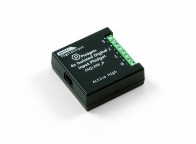
Digital Inputs can be used to convey the state of various devices such as push buttons, limit switches, relays, or logic level outputs. They have two states: high and low. Any signal that is expected to interact with more than just these 2 states is inappropriate for this type of input.
Digital inputs are one of the easiest components to work with, since all that is required is a simple check to see which state they are in when an event triggers. A digital input can either be Active High or Active Low:
- Active Low digital inputs consider their state to be TRUE when the voltage is low (closer to 0V), and FALSE when high (closer to 5V).
- Active High digital inputs are the opposite- TRUE when the voltage is high, and FALSE when the voltage is low.
The exact voltage values at which a digital input switches varies from device to device. See the specification table for your Phidget for more details.
Below is a table of Phidgets with digital inputs, and their type of digital input:
| Product # | Name | Digital Input Type |
| 1010 | PhidgetInterfaceKit 8/8/8 Mini-Format | Active Low |
| 1011 | PhidgetInterfaceKit 2/2/2 | Active Low |
| 1012 | PhidgetInterfaceKit 0/16/16 | Active High |
| 1018 | PhidgetInterfaceKit 8/8/8 | Active Low |
| 1019 | PhidgetInterfaceKit 8/8/8 w/6 Port Hub | Active Low |
| 1073 | PhidgetSBC3 | Active Low |
| 1203 | PhidgetTextLCD | Active Low |
| DAQ1200 | 4x Digital Input Phidget | Active Low |
| DAQ1300 | 4x Isolated Digital Input Phidget | Active High |
| DAQ1301 | 16x Isolated Digital Input Phidget | Active High |
| HUB0000 | VINT Hub Phidget | Active Low |
Specifications
Digital Input Hardware Filter
There is built-in filtering on the digital input, to eliminate false triggering from electrical noise. The digital input is first RC filtered by a 15K/100nF node, which will reject noise of higher frequency than 1kHz. This filter generally eliminates the need to shield the digital input from inductive and capacitive coupling likely to occur in wiring harnesses. You can further reduce noise by externally filtering the input signal, but you will lose sensitivity in the process.
Digital Input Hysteresis
The digital input has hysteresis - that is, it will hold its current state (false or true), unless a large change occurs. To guarantee FALSE, the digital input must be at least 3.75V, and to guarantee TRUE, the digital input must be less than 1.25V.
Digital Input Sampling Characteristics
The state of the digital inputs are reported back to the PC periodically. During this sampling period, if a digital input was true for greater than 4.0ms, the digital input is guaranteed to be reported as true in software. This makes the digital input much more sensitive to reporting TRUE state, and makes it useful to watch for short events. Any Digital Input True events of less than 1.5ms are never reported.
Electrical Specifications
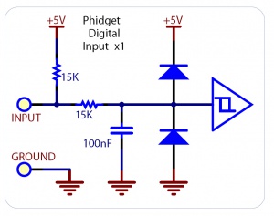
The digital inputs have a built in pull-up resistor. (It may be a 10 kOhm or 15 kOhm resistor depending on the Phidget). By connecting external circuitry, and forcing the input to Ground, the Digital Input in software will read as TRUE. The default state is FALSE - when you have nothing connected, or your circuitry (switch, etc) is not pulling the input to ground.
Using the Digital Inputs
Here are some circuit diagrams that illustrate how to connect various devices to the digital inputs on your Phidget.
Wiring a switch to a Digital Input
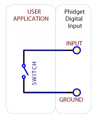
Closing or opening the switch causes the digital input to change state.
Monitoring the Position of a Relay
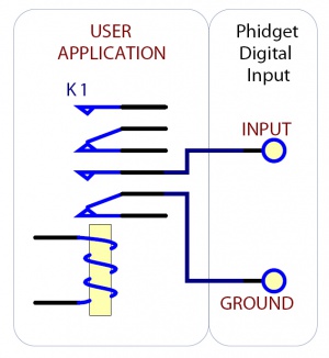
The relay contact can be treated as a switch, and wired up similarly. When the relay contact is opened or closed, the Digital Input's state will change.
Detecting an External Voltage with an N-Channel MOSFET
A MOSFET can be used to detect the presence of an external voltage. The external voltage will turn on the MOSFET, causing it to short the Digital Input to Ground. The voltage level required to turn on the MOSFET depends on the make of of MOSFET you are using. Typical values are 2V-6V.
Isolating a Digital Input with an Optocoupler
You can use an optocoupler to isolate a digital input from the device it's reading, which is useful for avoiding ground loops in some systems. The amount of current required will depend on the optocoupler used.
Detecting an External Voltage with an NPN Transistor
This circuit can be used to measure if a battery is connected, or if 12V (for example) is on a wire.
Using a Capacitive or Inductive Proximity Switch
Capacitive proximity switches can detect the presence of nearby non-metallic objects, whereas inductive proximity switches can detect only the presence of metallic objects. To properly interface one of these proximity switches to the digital inputs, a 3-wire proximity switch is required, as well as an external power supply. We have checked the following switch from Automation Direct to verify that it works with the Digital Inputs. Similar capacitive or inductive proximity switches from other manufacturers should work just as well.
| Manufacturer | Web Page | Capacitive Part No. | Inductive Part No. |
| Automation Direct | Automated Direct | CT1 Series | AM1 Series |
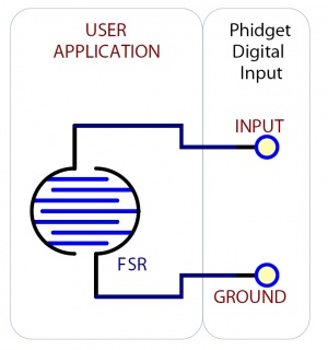
Using an FSR or Variable Resistor as a Switch
The digital inputs can be easily wired to use many variable resistors as switches. The digital input will activate either when the FSR is pressed, or when it is not pressed, depending on whether your digital input is active high or active low. You can adjust the sensitivity of the FSR by adding other resistors in series or parallel.