DCC1100 User Guide: Difference between revisions
No edit summary |
|||
| Line 38: | Line 38: | ||
{{ugAddressingInformation}} | {{ugAddressingInformation}} | ||
{{ugUsingYourOwnProgram| | {{ugUsingYourOwnProgram|DCC1100}} | ||
==Technical Details== | ==Technical Details== | ||
Revision as of 16:41, 17 October 2019
Getting Started
Welcome to the DCC1100 user guide! In order to get started, make sure you have the following hardware on hand:
- DCC1100 DC Motor Phidget
- VINT Hub
- Phidget Cable
- USB cable and computer
- Power supply (8-30V DC)
- Brushless DC motor
Next, you will need to connect the pieces:
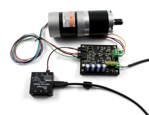
- Connect the DCC1100 to the VINT Hub using the Phidget cable.
- Connect the motor to the Phidget's output terminals. See the datasheet or product page for your motor to determine wiring.
- Connect the VINT Hub to your computer with a USB cable.
- Connect the motor's hall-effect wires to the 5-cable port on the DCC1100. If you didn't get your motor from our website, you'll want to solder half of a 3019 Cable to the end of the hall-effect wires.
- Connect the power supply to the power terminals.
Now that you have everything together, let's start using the DCC1100!
Using the DCC1100
Phidget Control Panel
In order to demonstrate the functionality of the DCC1100, the Phidget Control Panel running on a Windows machine will be used.
The Phidget Control Panel is available for use on both macOS and Windows machines.
Windows
To open the Phidget Control Panel on Windows, find the ![]() icon in the taskbar. If it is not there, open up the start menu and search for Phidget Control Panel
icon in the taskbar. If it is not there, open up the start menu and search for Phidget Control Panel
macOS
To open the Phidget Control Panel on macOS, open Finder and navigate to the Phidget Control Panel in the Applications list. Double click on the ![]() icon to bring up the Phidget Control Panel.
icon to bring up the Phidget Control Panel.
For more information, take a look at the getting started guide for your operating system:
Linux users can follow the getting started with Linux guide and continue reading here for more information about the DCC1100.
First Look
After plugging the DCC1100 into your computer and opening the Phidget Control Panel, you will see something like this:
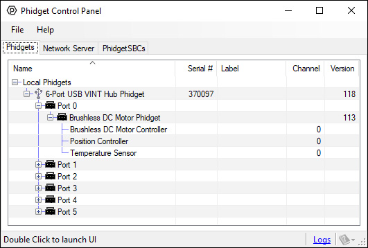
The Phidget Control Panel will list all connected Phidgets and associated objects, as well as the following information:
- Serial number: allows you to differentiate between similar Phidgets.
- Channel: allows you to differentiate between similar objects on a Phidget.
- Version number: corresponds to the firmware version your Phidget is running. If your Phidget is listed in red, your firmware is out of date. Update the firmware by double-clicking the entry.
The Phidget Control Panel can also be used to test your device. Double-clicking on an object will open an example.
The objects associated with the DCC1100 are as follows:
- Brushless DC Motor Controller: Controls the velocity and current of the motor.
- Position Controller: This object controls the position of the motor using the hall effect sensor in the motor.
- Temperature Sensor: Measures the temperature of the DCC1100 so you can tell if it's overheating.
Brushless DC Motor Controller
Double-click on the Brushless DC Motor Controller object Brushless DC Motor Phidget in order to run the example:
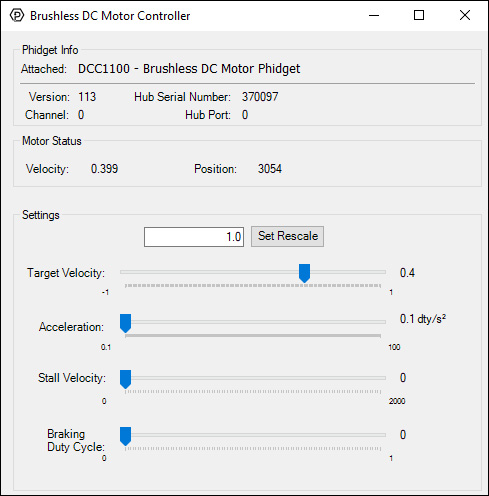
General information about the selected object will be displayed at the top of the window. You can also experiment with the following functionality:
- Change the motor speed by dragging the Target Velocity slider from -1 (maximum speed reverse) to 1 (maximum speed forward). You can see the updated Velocity and Position of the motor near the top of the window.
- Use the Acceleration slider to change how responsive the motor is to changes in Target Velocity.
- Use the Stall Velocity slider to control when the controller detects a stall. For more information, visit the API.
- Use the Braking Strength slider to determine how powerfully the motor will try to hold position when it is stopped. For more information, visit the API.
- Set the Rescale Value to change the position units, which is useful for converting to degrees or RPM. See the technical section of this guide for more details.
Position Controller
Double-click on the Position Controller object in order to run the example:
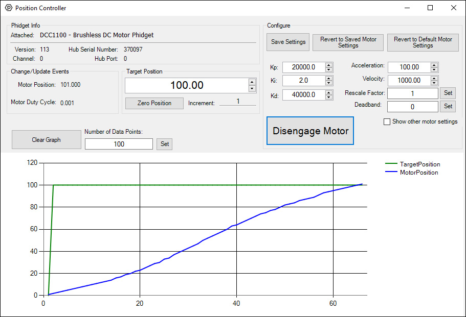
General information about the selected object will be displayed at the top of the window. You can also experiment with the following functionality:
Note: a video describing the use of this program is available below in the Technical Details section.
Configuration
- It is recommended to set the Rescale Factor first. This will change the units of your controller. For information on the rescale factor, visit the technical details section below.
- You can set the control parameters Kp, Ki and Kd in order to change the behavior of the control loop. You can save these variables into the program so you don't have to re-enter them manually (NOTE: This does not store the settings on the DCC1100, it simply saves them inside the control panel program, so you'll have to re-enter them if it's used on another computer).
- The Velocity Limit and '"Acceleration can be set in the top right. These values will be used to create a motion profile that the controller will try to track.
- Use the Deadband to determine how exactly the controller will try to reach the target position. View the API for a detailed description of how Deadband works.
- Click on Show Other Motor Settings' to access Stall Velocity. This is a safety feature which protects your hardware. View the API for a detailed description of how Stall Velocity works.
Other
- Change the Target Position to select which position you want the motor to try to reach.
- Press the Engage Motor button to allow the motor to start, and press again to stop it.
- You can Zero Position to add a position offset which will return the motor's position to 0.
Graph:
- You can view the control data on the graph. The green line is the selected target position, and the blue line is the motor's actual position as reported by the Hall Effect sensors. When the two lines meet, the motor will stop moving and attempt to hold that position, even if moved by an external force. You can Clear the graph, and customize the number of data points shown at any given time.
Temperature Sensor
Double-click on the Temperature Sensor object in order to run the example:
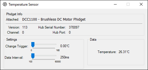
General information about the selected object will be displayed at the top of the window. You can also experiment with the following functionality:
- Modify the change trigger and/or data interval value by dragging the sliders. For more information on these settings, see the data interval/change trigger page.
- The measured temperature can be seen next to the Temperature label. Cover the board with your hands to see the temperature quickly rise.
Finding The Addressing Information
Before you can access the device in your own code, and from our examples, you'll need to take note of the addressing parameters for your Phidget. These will indicate how the Phidget is physically connected to your application. For simplicity, these parameters can be found by clicking the button at the top of the Control Panel example for that Phidget.

In the Addressing Information window, the section above the line displays information you will need to connect to your Phidget from any application. In particular, note the Channel Class field as this will be the API you will need to use with your Phidget, and the type of example you should use to get started with it. The section below the line provides information about the network the Phidget is connected on if it is attached remotely. Keep track of these parameters moving forward, as you will need them once you start running our examples or your own code.

Using Your Own Program
You are now ready to start writing your own code for the device. The best way to do that is to start from our Code Samples.
Select your programming language of choice from the drop-down list to get an example for your device. You can use the options provided to further customize the example to best suit your needs.
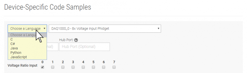
Once you have your example, you will need to follow the instructions on the page for your programming language to get it running. To find these instructions, select your programming language from the Programming Languages page.
Technical Details
Rescale Factor
Rescale factor can be set in order to change the units of the motor's position into something more useful, such as degrees or rotations. The following video explains how this is accomplished using a stepper controller as an example.
Instead of "steps", brushless DC motors work in "commutations". The number of commutations per rotation is equal to the number of poles multiplied by the number of phases. So if you have an 8-Pole, 3-Phase motor, it will have 24 commutations per rotation. In this case, you could set the rescale factor to 1/24, or 0.0416 in order for target position to be measured in rotations instead of commutations.
Control Loop Parameters
In order to get the desired behavior from your controller, you will have to tune your control parameters. This video explains the tuning procedure and gives information on how the controller works.
What to do Next
- Programming Languages - Find your preferred programming language here and learn how to write your own code with Phidgets!
- Phidget Programming Basics - Once you have set up Phidgets to work with your programming environment, we recommend you read our page on to learn the fundamentals of programming with Phidgets.