DCC1100 User Guide: Difference between revisions
No edit summary |
No edit summary |
||
| Line 1: | Line 1: | ||
__NOINDEX__ | __NOINDEX__ | ||
__NOTOC__ | |||
<metadesc>Control one brushless DC motor with the BLDC Motor Phidget. The hall effect input provides precise position control. Connects to a VINT Hub.</metadesc> | <metadesc>Control one brushless DC motor with the BLDC Motor Phidget. The hall effect input provides precise position control. Connects to a VINT Hub.</metadesc> | ||
[[Category:UserGuide]] | [[Category:UserGuide]] | ||
== | ==Part 1: Setup== | ||
{{UGIntro|DCC1100}} | {{UGIntro|DCC1100}} | ||
* [{{SERVER}}/products.php?product_id=DCC1100 DCC1100 DC Motor Phidget] | * [{{SERVER}}/products.php?product_id=DCC1100 DCC1100 DC Motor Phidget] | ||
| Line 23: | Line 24: | ||
Now that you have everything together, let's start using the DCC1100! | Now that you have everything together, let's start using the DCC1100! | ||
{{UGcontrolpanel|DCC1100}} | |||
{{ | == Part 2: Using Your Phidget == | ||
===About=== | |||
The DCC1100 lets you control one brushless DC motor with hall-effect feedback. With this Phidget, you can set the velocity (forward or reverse) and acceleration of your motor, or set a specific target position using the position controller built into the Phidgets software libraries. You can also monitor the controller temperature for cooling management and safety. | |||
The DCC1100 requires an 8-30V DC power supply. | |||
[[Image:DCC1100_About.jpg|link=|center]] | |||
===Explore Your Phidget Channels Using The Control Panel=== | |||
You can use your Control Panel to explore your Phidget's channels. | |||
'''1.''' Open your Control Panel, and you will find the following channels: | |||
[[Image:DCC1100_Panel.jpg|link=|center]] | |||
'''2.''' Double click on a channel to open an example program. Each channel belongs to a different channel class: | |||
{{UGC-Start}} | |||
{{UGC-Entry|Brushless DC Motor Controller| Controls the velocity and acceleration of the motor | |||
| | |||
In your Control Panel, double click on "Brushless DC Motor Controller": | |||
[[Image:DCC1100-BLDC.jpg|center|850px|link=]]}} | |||
{{UGC-Entry|Position Controller| A built-in PID position controller | |||
| | |||
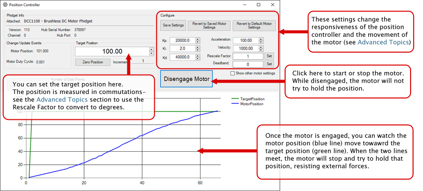
In your Control Panel, double click on "Position Controller": | |||
[[Image:DCC1100-PositionController.jpg|850px|center|link=]]}} | |||
{{UGC-Entry|Temperature Sensor| Measures the board temperature so you can tell if the DCC1100 is overheating | |||
| | |||
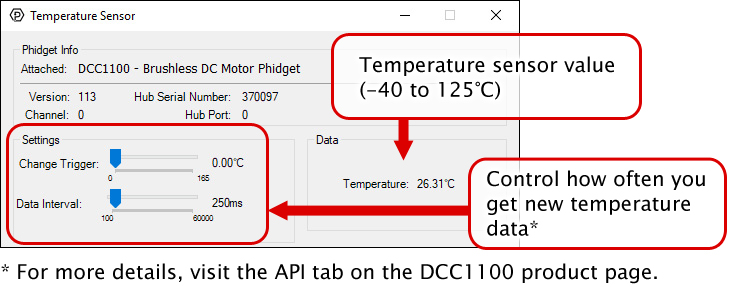
In your Control Panel, double click on "Temperature Sensor": | |||
[[Image:DCC1100-TemperatureSensor.jpg|center|link=]]}} | |||
{{UGC-End}} | |||
{{UG-Part3}} | |||
== Part 4: Advanced Topics and Troubleshooting == | |||
{{UGC-Start}} | |||
{{UGC-Addressing}} | |||
{{UGC-DataInterval}} | |||
{{ | {{UGC-Entry|Rescale Factor| | ||
| | |||
Rescale Factor can be set to change the motor position units into something more useful, such as degrees or rotations. The following video explains how to set the Rescale Factor using a stepper controller as an example. | |||
{{ | {{#ev:youtube|l0n9P9SmNVA|||||rel=0}} | ||
Instead of steps, brushless DC motors work in ''commutations''. The number of commutations per rotation is equal to the number of poles multiplied by the number of phases. So, if you have an 8-Pole, 3-Phase motor, the motor will have 24 commutations per rotation. For this motor, to change the target position units from communications to rotations, you would set the rescale factor to 1/24, or 0.0416. | |||
}} | |||
{{UGC-ControlLoopParams}} | |||
{{UGC-Entry|My motor moves away from the target position in Position Controller mode.| | |||
| | |||
Check your motor wires are hooked up correctly to the A B C terminals. Of the six possible wiring permutations, only one will result in normal rotation. | |||
Four of the wiring permutations will cause the motor to stall, and the other will cause reverse rotation. | |||
Check your motor’s datasheet for the correct wiring. }} | |||
{{UGC-End}} | |||
Revision as of 19:01, 27 May 2020
Part 1: Setup
Welcome to the DCC1100 user guide! In order to get started, make sure you have the following hardware on hand:
- DCC1100 DC Motor Phidget
- VINT Hub
- Phidget Cable
- USB cable and computer
- Power supply (8-30V DC)
- Brushless DC motor
Next, you will need to connect the pieces:
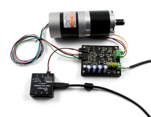
- Connect the DCC1100 to the VINT Hub using the Phidget cable.
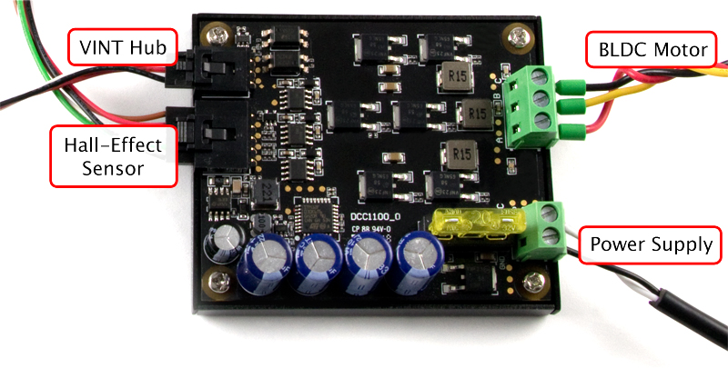
- Connect the motor to the Phidget's output terminals. See the datasheet or product page for your motor to determine wiring.
- Connect the VINT Hub to your computer with a USB cable.
- Connect the motor's hall-effect wires to the 5-cable port on the DCC1100. If you didn't get your motor from our website, you'll want to solder half of a 3019 Cable to the end of the hall-effect wires.
- Connect the power supply to the power terminals.
Now that you have everything together, let's start using the DCC1100!
Phidget Control Panel
In order to demonstrate the functionality of the DCC1100, the Phidget Control Panel running on a Windows machine will be used.
The Phidget Control Panel is available for use on both macOS and Windows machines.
Windows
To open the Phidget Control Panel on Windows, find the ![]() icon in the taskbar. If it is not there, open up the start menu and search for Phidget Control Panel
icon in the taskbar. If it is not there, open up the start menu and search for Phidget Control Panel
macOS
To open the Phidget Control Panel on macOS, open Finder and navigate to the Phidget Control Panel in the Applications list. Double click on the ![]() icon to bring up the Phidget Control Panel.
icon to bring up the Phidget Control Panel.
For more information, take a look at the getting started guide for your operating system:
Linux users can follow the getting started with Linux guide and continue reading here for more information about the DCC1100.
First Look
After plugging the DCC1100 into your computer and opening the Phidget Control Panel, you will see something like this:
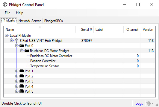
The Phidget Control Panel will list all connected Phidgets and associated objects, as well as the following information:
- Serial number: allows you to differentiate between similar Phidgets.
- Channel: allows you to differentiate between similar objects on a Phidget.
- Version number: corresponds to the firmware version your Phidget is running. If your Phidget is listed in red, your firmware is out of date. Update the firmware by double-clicking the entry.
The Phidget Control Panel can also be used to test your device. Double-clicking on an object will open an example.
Part 2: Using Your Phidget
About
The DCC1100 lets you control one brushless DC motor with hall-effect feedback. With this Phidget, you can set the velocity (forward or reverse) and acceleration of your motor, or set a specific target position using the position controller built into the Phidgets software libraries. You can also monitor the controller temperature for cooling management and safety.
The DCC1100 requires an 8-30V DC power supply.
Explore Your Phidget Channels Using The Control Panel
You can use your Control Panel to explore your Phidget's channels.
1. Open your Control Panel, and you will find the following channels:
2. Double click on a channel to open an example program. Each channel belongs to a different channel class:
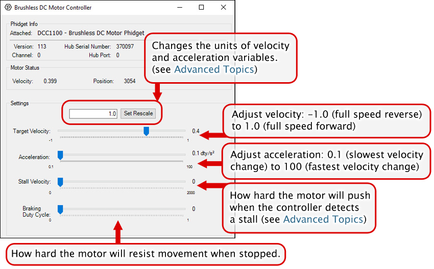
In your Control Panel, double click on "Brushless DC Motor Controller":
In your Control Panel, double click on "Position Controller":
In your Control Panel, double click on "Temperature Sensor":
Part 3: Create your Program
1. Setting up your Programming Environment
Part 4: Advanced Topics and Troubleshooting
Before you open a Phidget channel in your program, you can set these properties to specify which channel to open. You can find this information through the Control Panel.
1. Open the Control Panel and double-click on the red map pin icon:

2. The Addressing Information window will open. Here you will find all the information you need to address your Phidget in your program.

See the Phidget22 API for your language to determine exact syntax for each property.
The Change Trigger is the minimum change in the sensor data needed to trigger a new data event.
The Data Interval is the time (in ms) between data events sent out from your Phidget.
The Data Rate is the reciprocal of Data Interval (measured in Hz), and setting it will set the reciprocal value for Data Interval and vice-versa.
You can modify one or both of these values to achieve different data outputs. You can learn more about these properties here.
Rescale Factor can be set to change the motor position units into something more useful, such as degrees or rotations. The following video explains how to set the Rescale Factor using a stepper controller as an example.
Instead of steps, brushless DC motors work in commutations. The number of commutations per rotation is equal to the number of poles multiplied by the number of phases. So, if you have an 8-Pole, 3-Phase motor, the motor will have 24 commutations per rotation. For this motor, to change the target position units from communications to rotations, you would set the rescale factor to 1/24, or 0.0416.
In order to get the desired behavior from your controller, you will have to tune your control parameters. This video explains the tuning procedure and gives information on how the controller works.
Check your motor wires are hooked up correctly to the A B C terminals. Of the six possible wiring permutations, only one will result in normal rotation.
Four of the wiring permutations will cause the motor to stall, and the other will cause reverse rotation.
Check your motor’s datasheet for the correct wiring.