DCC1000 User Guide
Part 1: Setup
Welcome to the DCC1000 user guide! In order to get started, make sure you have the following hardware on hand:
- DCC1000 DC Motor Phidget
- VINT Hub
- Phidget cable
- USB cable and computer
- Power supply (8-30V DC)
- DC motor
Next, you will need to connect the pieces:
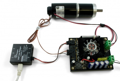
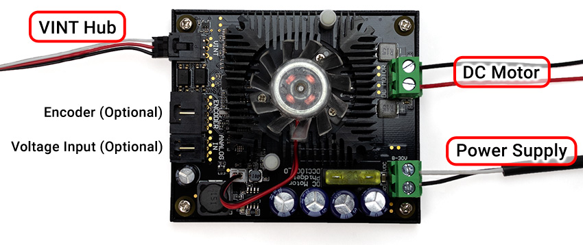
- Connect the DCC1000 to the VINT Hub using the Phidget cable.
- Connect the motor to the Phidget's output terminals.
- Connect the VINT Hub to your computer with a USB cable.
- (Optional) If your motor has an encoder, connect it to the encoder port on the DCC1000.
- Connect the power supply to the power terminals.
Now that you have everything together, let's start using the DCC1000!
Phidget Control Panel
In order to demonstrate the functionality of the DCC1000, the Phidget Control Panel running on a Windows machine will be used.
The Phidget Control Panel is available for use on both macOS and Windows machines.
Windows
To open the Phidget Control Panel on Windows, find the ![]() icon in the taskbar. If it is not there, open up the start menu and search for Phidget Control Panel
icon in the taskbar. If it is not there, open up the start menu and search for Phidget Control Panel
macOS
To open the Phidget Control Panel on macOS, open Finder and navigate to the Phidget Control Panel in the Applications list. Double click on the ![]() icon to bring up the Phidget Control Panel.
icon to bring up the Phidget Control Panel.
For more information, take a look at the getting started guide for your operating system:
Linux users can follow the getting started with Linux guide and continue reading here for more information about the DCC1000.
First Look
After plugging the DCC1000 into your computer and opening the Phidget Control Panel, you will see something like this:
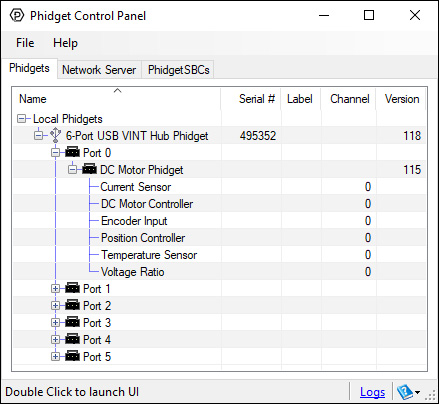
The Phidget Control Panel will list all connected Phidgets and associated objects, as well as the following information:
- Serial number: allows you to differentiate between similar Phidgets.
- Channel: allows you to differentiate between similar objects on a Phidget.
- Version number: corresponds to the firmware version your Phidget is running. If your Phidget is listed in red, your firmware is out of date. Update the firmware by double-clicking the entry.
The Phidget Control Panel can also be used to test your device. Double-clicking on an object will open an example.
Part 2: Using Your Phidget
About
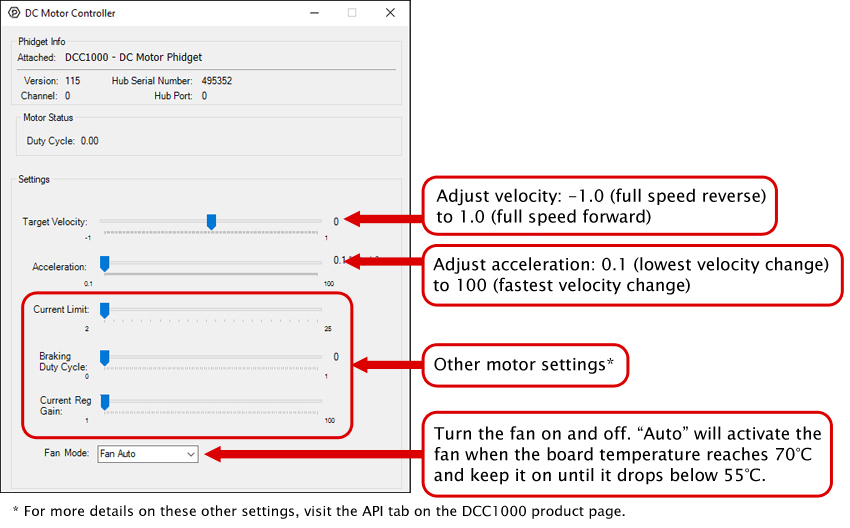
The DCC1000 allows you to control a DC motor or DC linear actuator. With this Phidget, you can control your motor by:
- Setting the velocity and acceleration with the DC Motor Controller
- Setting a specific target position using the Motor Position Controller (requires an encoder)
You can use the DCC1000 to monitor current passing through the motor, connect and monitor the motor’s potentiometer, and monitor the temperature of the motor.
Explore Your Phidget Channels Using the Control Panel
You can use your Control Panel to explore your Phidget's channels.
1. Open your Control Panel, and you will find the following channels:
2. Double click on a channel to open an example program. Each channel belongs to one of these channel classes:
In your Control Panel, double click on "DC Motor Controller":
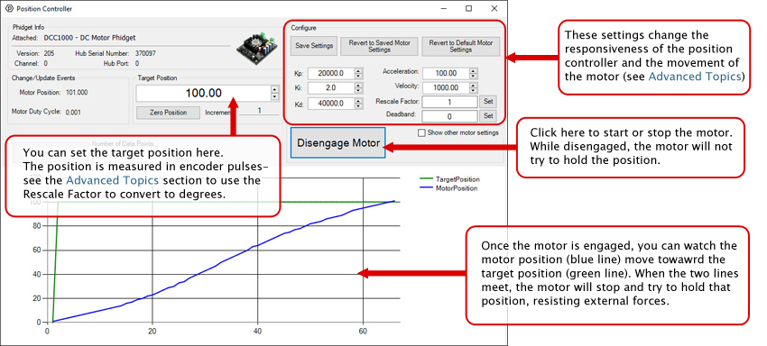
In your Control Panel, double click on "Position Controller":
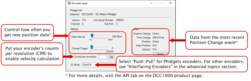
In your Control Panel, double click on "Encoder Input":
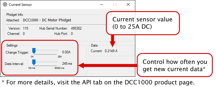
In your Control Panel, double click on "Current Sensor":
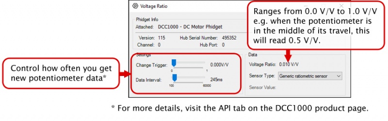
In your Control Panel, double click on "Voltage Ratio":
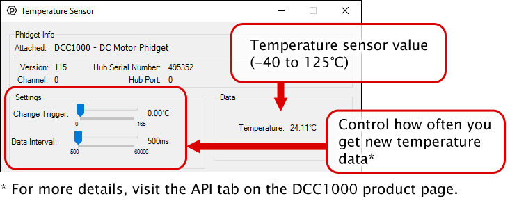
In your Control Panel, double click on "Temperature Sensor":
Part 3: Create your Program
1. Setting up your Programming Environment
Part 4: Advanced Topics and Troubleshooting
There are a number of settings that can be adjusted to customize the position controller. You can save these variables into the program so you don't have to re-enter them manually (NOTE: This does not store the settings on the DCC1000, it simply saves them inside the control panel program, so you'll have to re-enter them if it's used on another computer).
Kp, Ki, and Kd
You can set the control parameters Kp, Ki, and Kd in order to change the behavior of the control loop. For more information on how each of these three tuning parameters affect the control loop, see “Control Loop Parameters ”.
Velocity and Acceleration
Velocity is how fast the motor will move to the target position, and acceleration controls how quickly the motor will reach its velocity and how quickly it will slow down. These values are measured in position per second and position per second squared, and position by default is measured in encoder pulses.
Rescale Factor
If you want position to be measured in another unit (degrees, for example), you can set the rescale factor. For more information on choosing the correct rescale factor, see “Setting the Rescale Factor”.
Deadband
Sometimes the motor will oscillate back and forth across the target position when holding position. Adding a deadband will widen the target position so the motor will stop when it gets within the target position plus or minus the deadband.
Current Limit
Setting the current limit gives you control over how much power is being supplied to the motor. Generally, we advise that you set the current limit to your motor’s specified coil current.
Fan Mode
This turns the cooling fan on and off. Setting it to auto will result in the fan turning on only when the temperature sensor detects rising board temperatures.
Encoder IO Mode
Changes between different encoder modes based on your encoder’s circuitry. For more information see the Encoder Primer.
Current Regulator Gain
Depending on power supply voltage and motor coil inductance, the current through the motor can change relatively slowly or extremely rapidly. A physically larger DC Motor will typically have a lower inductance, requiring a higher current regulator gain. A higher power supply voltage will result in motor current changing more rapidly, requiring a higher current regulator gain. If the current regulator gain is too small, spikes in current will occur, causing large variations in torque, and possibly damaging the motor controller. If the current regulator gain is too high, the current will jitter, causing the motor to sound 'rough', especially when changing directions.
In order to get the desired behavior from your controller, you will have to tune your control parameters. This video explains the tuning procedure and gives information on how the controller works.
The DCC1000 can connect to any of the encoders we sell without any modification just by setting the EncoderIOMode property to Push-Pull . If you're trying to use your own encoder, you may need to change the IO mode to Open Collector or Line Driver mode. Have a look at the Encoder Primer for more details on what to use.
There are three pieces of information to consider when setting a rescale factor to change your units into degrees or rotations:
- Your encoder's CPR (counts per rotation)
- Your encoder interface's resolution
- Your motor's gear ratio
First, check your encoder's datasheet for the CPR. It's usually 360 or 300. This is the number of quadrature cycles the encoder will send out for one full rotation.
Next, you need your encoder interface's resolution. The encoder port on the DCC1000 has a x4 resolution, meaning it reads in 4 pulses per quadrature cycle (see the Encoder Primer for a more in-depth explanation).
Next, you need to find out the gear ratio in your motor's datasheet. Note: If you plan on having your motor run for many rotations in a row, try to find the exact gear ratio, expressed as a fraction. Using the rounded value will result in accumulating errors the more you rotate.
Once you have these numbers, you can calculate the rescale factor:
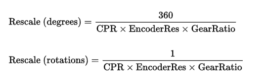
For example, if you wanted to have your motor's position measured in degrees and your encoder had 300 CPR and your motor had a 50 801⁄895 : 1 gearbox, you would set your rescale factor to 360 / 300*4*(50+(801/895)), or 0.005894.
The Change Trigger is the minimum change in the sensor data needed to trigger a new data event.
The Data Interval is the time (in ms) between data events sent out from your Phidget.
The Data Rate is the reciprocal of Data Interval (measured in Hz), and setting it will set the reciprocal value for Data Interval and vice-versa.
You can modify one or both of these values to achieve different data outputs. You can learn more about these properties here.
Reverse your motor’s wires. The control loop has to make an assumption about what direction your motor moves with a positive voltage, and in this case, the assumption was incorrect. Don’t worry, DC motors are fine being wired up backward since they’re essentially just a long loop of wire on the inside.