DAQ1400 User Guide
Part 1: Setup
Welcome to the DAQ1400 user guide! In order to get started, make sure you have the following hardware on hand:
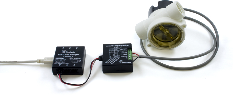
- DAQ1400 - Versatile Input Phidget
- VINT Hub
- Phidget cable
- USB cable and computer
- something to use with the DAQ1400 (e.g. 4-20mA sensor, frequency output device, etc.)
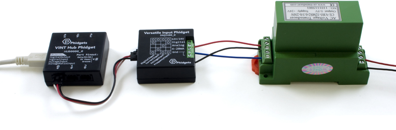
Next, you will need to connect the pieces:
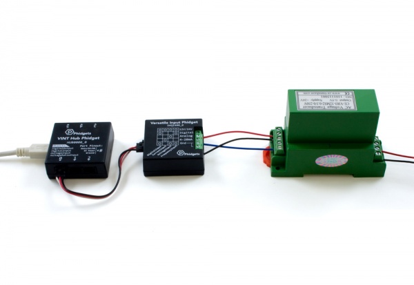
- Connect the DAQ1400 to the VINT Hub using the Phidget cable.
- Connect the VINT Hub to your computer with a USB cable.
- Connect sensor or device to the appropriate input on the DAQ1400. For details, see the technical section.
Now that you have everything together, let's start using the DAQ1400!
Phidget Control Panel
In order to demonstrate the functionality of the DAQ1400, the Phidget Control Panel running on a Windows machine will be used.
The Phidget Control Panel is available for use on both macOS and Windows machines.
Windows
To open the Phidget Control Panel on Windows, find the ![]() icon in the taskbar. If it is not there, open up the start menu and search for Phidget Control Panel
icon in the taskbar. If it is not there, open up the start menu and search for Phidget Control Panel
macOS
To open the Phidget Control Panel on macOS, open Finder and navigate to the Phidget Control Panel in the Applications list. Double click on the ![]() icon to bring up the Phidget Control Panel.
icon to bring up the Phidget Control Panel.
For more information, take a look at the getting started guide for your operating system:
Linux users can follow the getting started with Linux guide and continue reading here for more information about the DAQ1400.
First Look
After plugging the DAQ1400 into your computer and opening the Phidget Control Panel, you will see something like this:
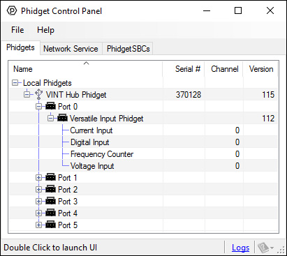
The Phidget Control Panel will list all connected Phidgets and associated objects, as well as the following information:
- Serial number: allows you to differentiate between similar Phidgets.
- Channel: allows you to differentiate between similar objects on a Phidget.
- Version number: corresponds to the firmware version your Phidget is running. If your Phidget is listed in red, your firmware is out of date. Update the firmware by double-clicking the entry.
The Phidget Control Panel can also be used to test your device. Double-clicking on an object will open an example.
Part 2: Using Your Phidget
About
The Versatile Input Phidget is designed to connect to NPN/PNP digital sensors, 4-20mA sensors, 0-5V analog sensors that require 12/24V power supply, and pulse output sensors. The DAQ1400 is a general-purpose adapter to get almost any sensor working with Phidgets.
Explore Your Phidget Channels Using The Control Panel
You can use your Control Panel to explore your Phidget's channels.
1. Open your Control Panel, and you will find the following channels:
2. Double click on a channel to open an example program. Each channel belongs to a different channel class:
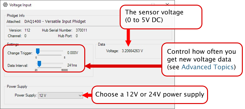
In your Control Panel, double click on "Voltage Input":
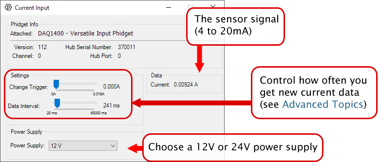
In your Control Panel, double click on "Current Input":
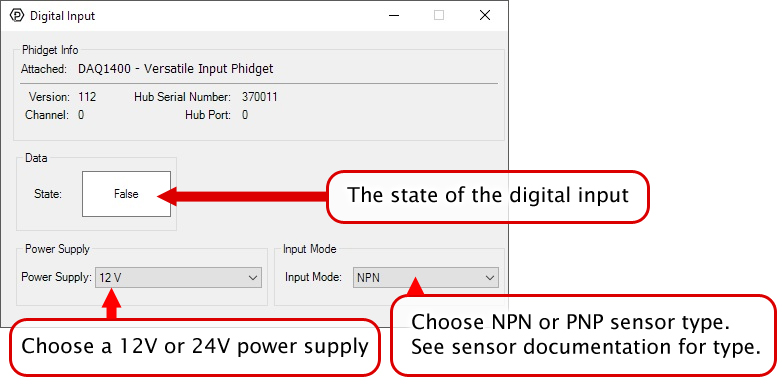
In your Control Panel, double click on "Digital Input":
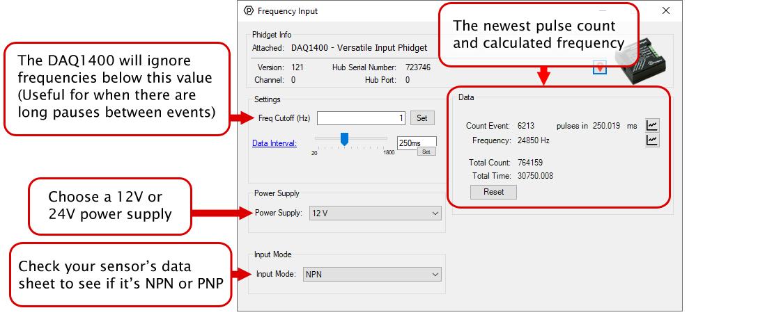
In your Control Panel, double click on "Frequency Counter":
Part 3: Create your Program
1. Setting up your Programming Environment
Part 4: Advanced Topics and Troubleshooting
Before you open a Phidget channel in your program, you can set these properties to specify which channel to open. You can find this information through the Control Panel.
1. Open the Control Panel and double-click on the red map pin icon:

2. The Addressing Information window will open. Here you will find all the information you need to address your Phidget in your program.

See the Phidget22 API for your language to determine exact syntax for each property.
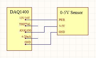
This mode measures an input between 0V and 5V. To connect your 0-5V sensor to the DAQ1400, wire the sensor to the terminals as pictured in the diagram. You may need to refer to the datasheet for your sensor to determine which wire is which.
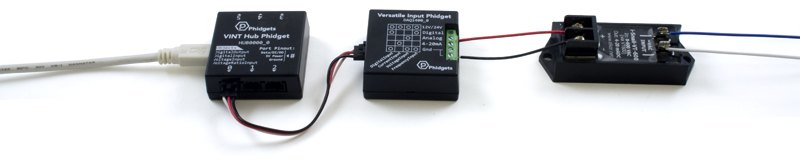
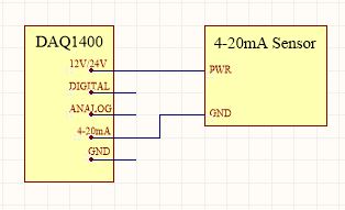
This mode is designed to interface a 4-20mA sensor, which is a common industrial standard. To connect your 4-20mA sensor to the DAQ1400, wire the sensor to the terminals as pictured in the diagram.
Even though this mode is intended for this specific purpose, you can also use it as a general-purpose current sensor, in which case it can measure current values between 0.5mA and 20mA (Measuring below 0.5mA is not recommended).
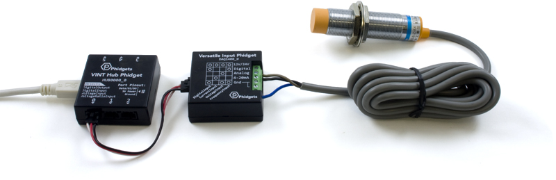
Some industrial sensors have a simple true/false value which can be read by a digital input. Many proximity or movement sensors have this kind of output. It is common that these sensors will require a 12V or 24V power supply, so other Digital Input Phidgets are not a complete solution in this case. A digital sensor will either be PNP or NPN:
- An NPN sensor will switch the sensor line to ground whenever the sensor activates.
- A PNP sensor will switch the sensor line to power whenever the sensor activates.
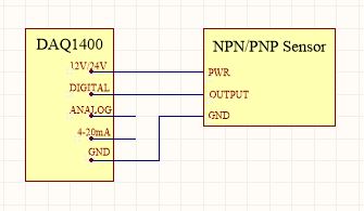
Normally, you'd need a different kind of digital input to interface these two types of sensors. Luckily, the DAQ1400 can read either one; all you have to do is set the Input Mode property to the correct type (see the Phidget22 API for details). To connect your digital sensor to the DAQ1400, wire the sensor to the terminals as pictured in the diagram.
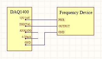
Sensors that measure using rotation such as flow meters or anemometers usually have a pulse output. For example, a flow sensor might send a 5V pulse down the line every time the turbine makes a full rotation. Using this information with timestamps, you can calculate the turbine speed. While you could theoretically use a Phidget with a Digital Input to read this kind of signal, most digital input boards are not designed to read pulse signals that change this frequently, so they will miss pulses and calculate the wrong speed. The DAQ1400 is specially designed to read these high frequency pulse signals when in Frequency Input mode.
To connect your sensor to the DAQ1400, wire the sensor to the terminals as pictured in the diagram.
If your sensor frequency is faster than 600Hz, you may seem to be 'maxing out' the DAQ1400. This is because the pull-down resistance is too weak to pull the signal down. To strengthen the pull-down, put a 10KΩ resistor across the Digital and Gnd terminals.