DAQ1200 User Guide: Difference between revisions
No edit summary |
|||
| (21 intermediate revisions by 3 users not shown) | |||
| Line 1: | Line 1: | ||
__NOINDEX__ | |||
__NOTOC__ | |||
<metadesc>Add 4 digital inputs to your VINT Hub with the 4x Digital Input Phidget. These inputs react faster than a VINT port in Digital Input mode.</metadesc> | |||
[[Category:UserGuide]] | [[Category:UserGuide]] | ||
== Part 1: Setup == | |||
{{UGIntro|DAQ1200}} | |||
*[{{SERVER}}/products.php?product_id=DAQ1200 DAQ1200 - 4x Digital Input Phidget] | |||
* {{VINTHub}} | |||
* | * {{CT|PhidgetCable|Phidget cable}} | ||
* | * USB cable and computer | ||
* | * something to use with the DAQ1200 (e.g. switch or digital sensor with a digital output) | ||
* | |||
* | |||
Next, you will need to connect the pieces: | |||
[[Image:DAQ1200_Functional.jpeg|600px|right|link=]] | |||
# Connect the DAQ1200 to the VINT Hub using the Phidget cable. | # Connect the DAQ1200 to the VINT Hub using the Phidget cable. | ||
# Connect the VINT Hub to your computer with a USB cable. | # Connect the VINT Hub to your computer with a USB cable. | ||
# Connect a switch or digital sensor to one of the DAQ1200's | # Connect a switch or digital sensor to one of the DAQ1200's inputs. | ||
<br clear="all"> | <br clear="all"> | ||
{{UGIntroDone|DAQ1200}}. | |||
{{UGcontrolpanel|DAQ1200}} | |||
== Part 2: Using Your Phidget == | |||
===About=== | |||
Read four digital output devices with the DAQ1200. This Phidget is best suited for reading switches, or 5V logic level devices. | |||
The DAQ1200 is an active-low device. You interact with the DAQ1200 through the Digital Input Channel Class. The Digital Input state equals ''true'' when grounded and ''false'' when connected to a high voltage. | |||
===Explore Your Phidget Channels Using The Control Panel=== | |||
You can use your Control Panel to explore your Phidget's channels. | |||
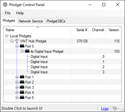
'''1.''' Open your Control Panel, and you will find the following channels: | |||
[[Image:DAQ1200_Panel.jpg|link=|center]] | |||
'''2.''' Double click on a channel to open an example program. Each channel belongs to the '''Digital Input''' channel class: | |||
{{ | {{UGC-Start}} | ||
{{UGC-Entry|Digital Input:| Read the state of a 5V digital signal| | |||
In your Control Panel, double click on "Digital Input": | |||
[[Image:DAQ1200-test-DigitalInput.jpg|center|link=]]}} | |||
For more information about Digital Inputs, take a look at the [[Digital Input Primer]]. | |||
{{ | {{UGC-End}} | ||
{{ | {{UG-Part3}} | ||
== | == Part 4: Advanced Topics and Troubleshooting == | ||
{{UGC-Start}} | |||
{{UGC-Addressing}} | |||
{{UGC-Entry|Using the DAQ1200 with a Switch|| | |||
[[Image:DAQ1200_SwitchInput.jpg|link=|350px|right]] | |||
To interface a switch with the DAQ1200, simply connect the switch across the input and ground terminals for a channel. | |||
}} | |||
{{UGC-Entry|Using the DAQ1200 with 5V Logic Level Devices|| | |||
[[Image:DAQ1200_LogicInput.jpg|link=|350px|right]] | |||
The DAQ1200 can also detect signals from 5V logic level devices. Be aware that the input is active-low, which means that LOW voltages will be detected as TRUE, and HIGH voltages as FALSE. | |||
}} | |||
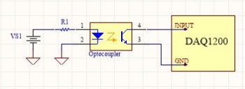
{{UGC-Entry|Isolation with Optocouplers|| | |||
[[Image:DAQ1200_Optocoupler_Diagram.jpg|link=|350px|right]] | |||
In some applications, particularly where there is a lot of electrical noise (automotive), or where you want maximum protection of the circuitry (interactive installations, kiosks), electrical isolation buys you a huge margin of protection. | |||
If wired according to the diagram, driving the LED will cause the DAQ1200 to report TRUE. | |||
{{ | Note that in cases where many isolated inputs are required, or for simplicity's sake, you may want to consider using the {{Prod|DAQ1300}} or {{Prod|DAQ1301}}, which are (more sophisticated) ready-made isolated digital input Phidgets. | ||
}} | |||
{{UGC-End}} | |||
Revision as of 18:17, 21 April 2020
Part 1: Setup
Welcome to the DAQ1200 user guide! In order to get started, make sure you have the following hardware on hand:
- DAQ1200 - 4x Digital Input Phidget
- VINT Hub
- Phidget cable
- USB cable and computer
- something to use with the DAQ1200 (e.g. switch or digital sensor with a digital output)
Next, you will need to connect the pieces:
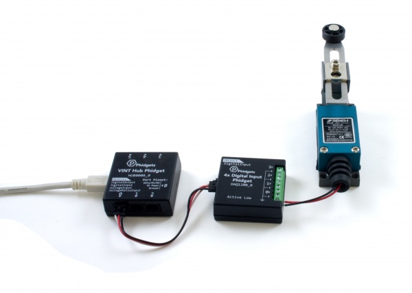
- Connect the DAQ1200 to the VINT Hub using the Phidget cable.
- Connect the VINT Hub to your computer with a USB cable.
- Connect a switch or digital sensor to one of the DAQ1200's inputs.
Now that you have everything together, let's start using the DAQ1200!.
Phidget Control Panel
In order to demonstrate the functionality of the DAQ1200, the Phidget Control Panel running on a Windows machine will be used.
The Phidget Control Panel is available for use on both macOS and Windows machines.
Windows
To open the Phidget Control Panel on Windows, find the ![]() icon in the taskbar. If it is not there, open up the start menu and search for Phidget Control Panel
icon in the taskbar. If it is not there, open up the start menu and search for Phidget Control Panel
macOS
To open the Phidget Control Panel on macOS, open Finder and navigate to the Phidget Control Panel in the Applications list. Double click on the ![]() icon to bring up the Phidget Control Panel.
icon to bring up the Phidget Control Panel.
For more information, take a look at the getting started guide for your operating system:
Linux users can follow the getting started with Linux guide and continue reading here for more information about the DAQ1200.
First Look
After plugging the DAQ1200 into your computer and opening the Phidget Control Panel, you will see something like this:
The Phidget Control Panel will list all connected Phidgets and associated objects, as well as the following information:
- Serial number: allows you to differentiate between similar Phidgets.
- Channel: allows you to differentiate between similar objects on a Phidget.
- Version number: corresponds to the firmware version your Phidget is running. If your Phidget is listed in red, your firmware is out of date. Update the firmware by double-clicking the entry.
The Phidget Control Panel can also be used to test your device. Double-clicking on an object will open an example.
Part 2: Using Your Phidget
About
Read four digital output devices with the DAQ1200. This Phidget is best suited for reading switches, or 5V logic level devices.
The DAQ1200 is an active-low device. You interact with the DAQ1200 through the Digital Input Channel Class. The Digital Input state equals true when grounded and false when connected to a high voltage.
Explore Your Phidget Channels Using The Control Panel
You can use your Control Panel to explore your Phidget's channels.
1. Open your Control Panel, and you will find the following channels:
2. Double click on a channel to open an example program. Each channel belongs to the Digital Input channel class:
In your Control Panel, double click on "Digital Input":
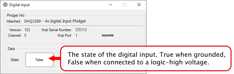
For more information about Digital Inputs, take a look at the Digital Input Primer.
Part 3: Create your Program
1. Setting up your Programming Environment
Part 4: Advanced Topics and Troubleshooting
Before you open a Phidget channel in your program, you can set these properties to specify which channel to open. You can find this information through the Control Panel.
1. Open the Control Panel and double-click on the red map pin icon:

2. The Addressing Information window will open. Here you will find all the information you need to address your Phidget in your program.

See the Phidget22 API for your language to determine exact syntax for each property.
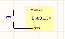
To interface a switch with the DAQ1200, simply connect the switch across the input and ground terminals for a channel.
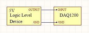
The DAQ1200 can also detect signals from 5V logic level devices. Be aware that the input is active-low, which means that LOW voltages will be detected as TRUE, and HIGH voltages as FALSE.
In some applications, particularly where there is a lot of electrical noise (automotive), or where you want maximum protection of the circuitry (interactive installations, kiosks), electrical isolation buys you a huge margin of protection.
If wired according to the diagram, driving the LED will cause the DAQ1200 to report TRUE.
Note that in cases where many isolated inputs are required, or for simplicity's sake, you may want to consider using the DAQ1300 or DAQ1301, which are (more sophisticated) ready-made isolated digital input Phidgets.