Analog Input Guide
Introduction
It is common for a sensor to output a voltage in order to relay information about what it is measuring. For example, the 1124 temperature sensor has the following characteristics:

| Measured Temperature (°C) | Output Voltage (V) |
| -50 | 0.25 |
| 0 | 1.37 |
| 150 | 4.75 |
This means that if you want to know what the temperature is (or pressure, humidity, position, etc.), you will need to measure the sensor's output voltage. In order to do this, you can use any of our Phidgets with an analog input. Each Phidget with an analog input interfaces with sensors using three wires (as shown in the image above):
- Power (+5 VDC) - provides the sensor with power.
- Ground
- Data - The sensor manipulates the voltage on this line. The Phidget measures and reports this voltage.
For information about different types of analog inputs, as well as the software objects that are used with analog inputs, visit the Phidgets Connectors page. Next, we will take a look at the connector that is commonly used for our sensors.
Connector
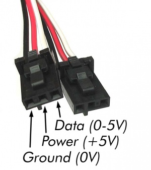
Each analog input uses a 3-pin, 0.100 inch pitch locking connector. Pictured here is a plug with the connections labeled.
The Phidget cables that are designed to plug into these inputs can be found here.
The connectors and pins they use are also commonly available (usually through digikey) - refer to the table below for manufacturer part numbers.
| Manufacturer | Part Number | Description |
| Molex | 50-57-9403 | 3 Position Cable Connector |
| Molex | 16-02-0102 | Wire Crimp Insert for Cable Connector |
| Molex | 70543-0002 | 3 Position Vertical PCB Connector |
| Molex | 70553-0002 | 3 Position Right-Angle PCB Connector (Gold) |
| Molex | 70553-0037 | 3 Position Right-Angle PCB Connector (Tin) |
| Molex | 15-91-2035 | 3 Position Right-Angle PCB Connector - Surface Mount |
Electrical Specifications
The maximum total current consumed by all analog inputs should be limited to 400mA. The voltage measurement is represented in the software through the Voltage property as a value between 0 and 5 volts. 5V corresponds to a high sensor value, and 0V corresponds to zero sensor activity.
The analog inputs on Phidgets InterfaceKits are designed for a maximum of 5V. More than this will cause unpredictable behaviour and could damage the board.
Connecting non-Phidget devices to the Analog Inputs
Here are some circuit diagrams that illustrate how to connect various non Phidgets devices to the analog inputs on your Phidget.
Sensing the Value of a Variable Resistance Sensor
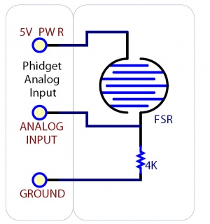
In this diagram, an FSR (Force Sensitive Resistor) is shown.
Sensing the Position of a Potentiometer
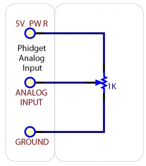
This diagram shows how to monitor the position of a potentiometer.
Interfacing to an Arbitrary Sensor
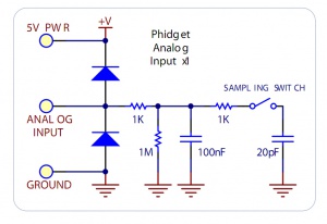
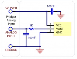
Normally, you can connect a sensor directly to the analog input as long as it has a 0-5V range (or smaller). However, if the sensor is not designed to send its signal across a long cable, you may need to add components as shown in the image.
Note the use of power supply decoupling and the RC Filter on the output. The RC filter also prevents VOUT from oscillating on many sensors.
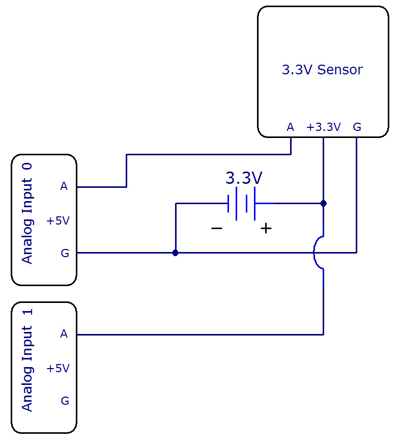
Interfacing 3.3V Sensors
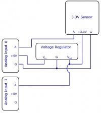
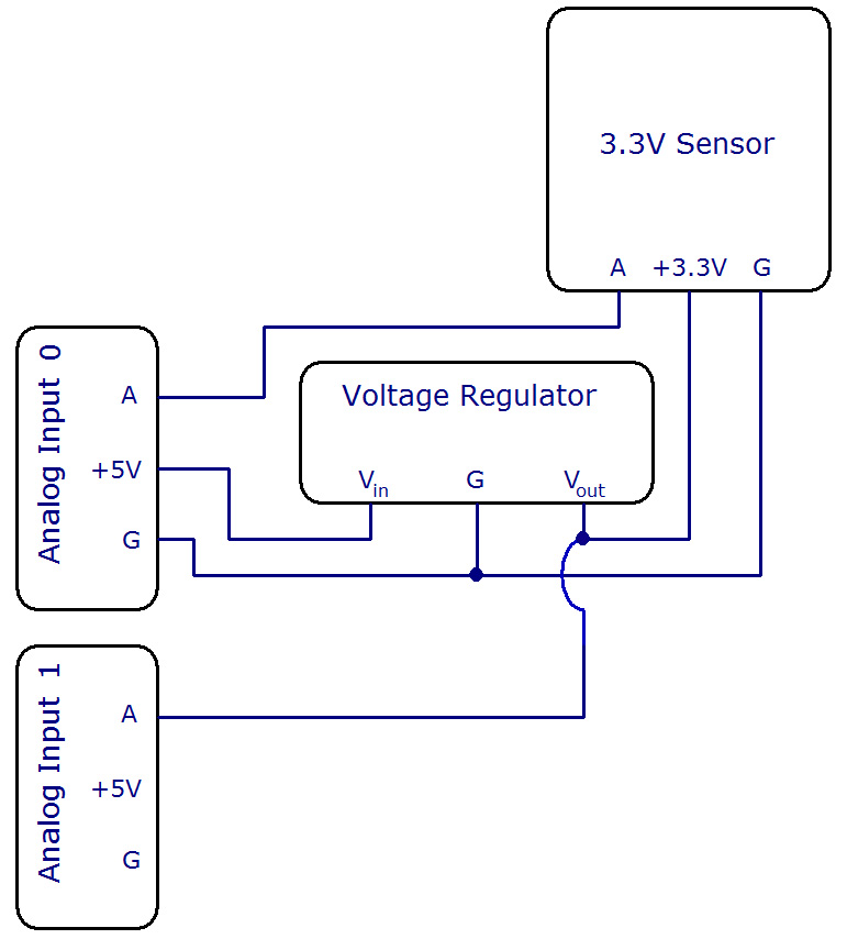
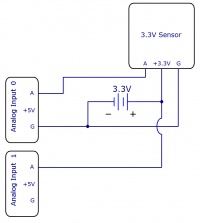
When using a 3.3V sensor with the analog input of a Phidget InterfaceKit, the main challenge is generating the 3.3V supply. You can either buy a 3.3V power supply, or you can buy a voltage regulator to convert the 5V line on the analog input to a 3.3V line, as illustrated in the diagrams. You can also use a second analog input to monitor the output of the 3.3V supply on the regulator.
Factors that can affect Accuracy
- High Output Impedance - Sensors that have a high output impedance will be distorted by the input impedance of the analog input.
If your output impedance is high, it is possible to correct for this distortion to some extent in your software application.
- Voltage Drop - Phidget cables have some resistance, which can cause voltage to drop across particularly long lengths of cable. For ratiometric sensors in particular, this can affect accuracy. Long cables also potentially expose the line to a greater amount of interference from surrounding electronics.
- Intrinsic Error In Sensors - For many sensors, the error is quite predictable by testing it alongside a more accurate sensor, and can be calibrated out in software.
- Voltage Reference - Voltage Reference error. The 5.0VDC voltage reference is accurate to 0.5%.
This can be a significant source of error in some applications, but can be easily measured and compensated for.