|
|
| (4 intermediate revisions by 2 users not shown) |
| Line 1: |
Line 1: |
| | <metadesc>Analog Inputs are used to read signals, that range from 0 to 5 volts DC. You can find analog sensors and interface boards at Phidgets.com.</metadesc> |
| [[Category:Primer]] | | [[Category:Primer]] |
|
| |
|
| Analog Inputs are used to interface many different types of sensors, such as temperature, humidity, position, or pressure sensors. There are three classes of Phidget products that can be used with these sensors:
| | ==Introduction== |
| | | It is common for a sensor to output a voltage in order to relay information about what it is measuring. For example, the 1124 temperature sensor has the following characteristics: |
| * Phidget InterfaceKits such as the [{{SERVER}}/products.php?product_id=1018 1018 - PhidgetInterfaceKit 8/8/8] have multiple voltage inputs.
| | [[File:Analoginput_tempsensor.jpg|link=|right|500px|The 1124]] |
| | {|class="wikitable" style="text-align: center; margin:auto;" |
| | |style="background:#f0f0f0;"|'''Measured Temperature (°C)''' |
| | |style="background:#f0f0f0;"|'''Output Voltage (V)''' |
| | |- |
| | | -50||0.25 |
| | |- |
| | |0||1.37 |
| | |- |
| | |150||4.75 |
| | |- |
| | |} |
| | <br clear="all"> |
|
| |
|
| * The ports on a Phidget {{VINTHub}} can be used to read sensors like an analog input. See the page on [[Phidgets Connectors]] for more information.
| |
|
| |
|
| * Some VINT devices like the [{{SERVER}}/products.php?product_id=DAQ1000 DAQ1000] add analog inputs to your VINT Hub.
| | This means that if you want to know what the temperature is (or pressure, humidity, position, etc.), you will need to measure the sensor's output voltage. In order to do this, you can use any of our [{{SERVER}}/?view=comparetable&rel=Analog%20Inputs Phidgets with an analog input]. Each Phidget with an analog input interfaces with sensors using three wires (as shown in the image above): |
| | *Power (+5 VDC) - provides the sensor with power. |
| | *Ground |
| | *Data - The sensor manipulates the voltage on this line. The Phidget measures and reports this voltage. |
|
| |
|
| Each analog input provides power (Nominal +5VDC), ground, and an analog voltage return wire driven by the sensor to some voltage.
| |
| The Interface Kit continuously measures this return voltage and reports it to the application.
| |
|
| |
|
| Phidgets offers a wide variety of sensors that can be plugged directly into the board using the cable included with the sensor.
| | For information about different types of analog inputs, as well as the software objects that are used with analog inputs, visit the [[Phidgets Connectors]] page. Next, we will take a look at the connector that is commonly used for our sensors. |
| | | ==Connector== |
| ==Mechanical Specifications== | |
| {{AnalogConnector}} | | {{AnalogConnector}} |
|
| |
|
| Line 27: |
Line 39: |
| The analog inputs on Phidgets InterfaceKits are designed for a maximum of 5V. More than this will cause unpredictable behaviour and could damage the board. | | The analog inputs on Phidgets InterfaceKits are designed for a maximum of 5V. More than this will cause unpredictable behaviour and could damage the board. |
| <br clear=all> | | <br clear=all> |
|
| |
| ==VoltageInput and VoltageRatioInput==
| |
| Each analog input can be opened as either a VoltageInput object or a VoltageRatioInput in software.
| |
|
| |
| For more details on the differences between these two objects, have a look at the [[Phidgets Connectors]] page.
| |
|
| |
| ==Factors that can affect Accuracy==
| |
|
| |
| *'''High Output Impedance''' - Sensors that have a high output impedance will be distorted by the input impedance of the analog input.
| |
| If your output impedance is high, it is possible to correct for this distortion to some extent in your software application.
| |
|
| |
| *'''Voltage Drop''' - Phidget cables have some resistance, which can cause voltage to drop across particularly long lengths of cable. For ratiometric sensors in particular, this can affect accuracy. Long cables also potentially expose the line to a greater amount of interference from surrounding electronics.
| |
|
| |
| *'''Intrinsic Error In Sensors''' - For many sensors, the error is quite predictable by testing it alongside a more accurate sensor, and can be calibrated out in software.
| |
|
| |
| *'''Voltage Reference''' - Voltage Reference error. The 5.0VDC voltage reference is accurate to 0.5%.
| |
| This can be a significant source of error in some applications, but can be easily measured and compensated for.
| |
|
| |
| <br clear="all">
| |
|
| |
| ==Changing the Data Interval==
| |
| You can change the data interval for each VoltageInput or VoltageRatioInput object in software.
| |
|
| |
| For analog inputs, 8 ms is the maximum transmission rate. This limit is set by the USB processor we use, so there isn't much you can do to get around it.
| |
|
| |
| For values less than 8 ms, the data interval sets the sampling rate, not the transmission rate.
| |
| If, for example, you set the data interval to 1ms, you will receive a packet containing 8 miliseconds worth of 1 ms samples every 8ms.
| |
| Setting the data interval to 1, 2, or 4ms will not allow you to react to received sensor data any faster than every 8ms;
| |
| You will simply get more data samples within the 8ms. This feature is useful if you need to log sensor data at less than 8 ms resolution but don't need to react to it in real-time.
| |
|
| |
| Setting the data interval of the analog inputs is (in some ways) an alternative to setting the [[#Changing the Change Trigger|change trigger]]. For details on how these two properties interact with one another, have a look at the [[Data Interval/Change Trigger]] page.
| |
|
| |
| There is also a limit as to how many channels can be set at a high sampling rate, since you will, at one point run out of bandwidth.
| |
| We estimate that you can set up to 4 channels to 1ms or you could set all channels to 2ms.
| |
| You can't turn channels off entirely to save bandwidth, you can only set them to a longer data interval.
| |
| You will get an error when you exceed the available bandwidth, warning you of lost data samples.
| |
|
| |
| Note that data interval is limited to at most 16ms when opening over the Phidget Webservice.
| |
| Actual data interval will depend on network latency.
| |
|
| |
| The method to change data interval is slightly different in each programming language; see the {{Phidget22API}} for more information.
| |
|
| |
| ==Changing the Change Trigger==
| |
|
| |
| You can change the change trigger of a sensor using the VoltageChangeTrigger or VoltageRatioChangeTrigger properties in software. You can think of change trigger as a minimum amount of change in voltage needed to register a change event in software. Whenever your sensor generates a new value, it will be compared to the change trigger. If the difference between the last triggered data point and the new data point is less than the change trigger value, no event will be generated.
| |
|
| |
| Setting the change trigger of an analog input is an (in some ways) an alternative to setting the [[#Changing the Data Interval|data interval]]. For details on how these two properties interact with one another, have a look at the [[Data Interval/Change Trigger]] page.
| |
|
| |
| The method to change the change trigger is slightly different in each programming language; see the {{Phidget22API}} for more information.
| |
|
| |
|
| ==Connecting non-Phidget devices to the Analog Inputs== | | ==Connecting non-Phidget devices to the Analog Inputs== |
| Line 112: |
Line 75: |
|
| |
|
| <br clear=all> | | <br clear=all> |
| | ==Factors that can affect Accuracy== |
|
| |
|
| ===Interfacing 4-20mA Sensors===
| | *'''High Output Impedance''' - Sensors that have a high output impedance will be distorted by the input impedance of the analog input. |
| | If your output impedance is high, it is possible to correct for this distortion to some extent in your software application. |
|
| |
|
| You can use the [{{SERVER}}/products.php?product_id=1132 1132 - 4-20mA Sensor Interface] to read a 4-20mA sensor with an analog input. For more information on 4-20mA sensors, see the [[4-20mA Sensor Interface Primer]].
| | *'''Voltage Drop''' - Phidget cables have some resistance, which can cause voltage to drop across particularly long lengths of cable. For ratiometric sensors in particular, this can affect accuracy. Long cables also potentially expose the line to a greater amount of interference from surrounding electronics. |
|
| |
|
| ==List of Devices with an Analog Input==
| | *'''Intrinsic Error In Sensors''' - For many sensors, the error is quite predictable by testing it alongside a more accurate sensor, and can be calibrated out in software. |
|
| |
|
| {{:Devices with Analog Inputs}}
| | *'''Voltage Reference''' - Voltage Reference error. The 5.0VDC voltage reference is accurate to 0.5%. |
| | This can be a significant source of error in some applications, but can be easily measured and compensated for. |
|
| |
|
| ==Non Phidgets 0-5V Sensors==
| | <br clear="all"> |
| | |
| In addition to Phidgets sensors, any sensor that returns a signal between 0 and 5 volts can be easily interfaced.
| |
| Here is a list of interesting sensors that can be used with the PhidgetInterfaceKit 8/8/8.
| |
| Note: these sensors are not “plug & play” like the sensors manufactured by Phidgets.
| |
| | |
| | |
| | |
| {| style="border:1px solid darkgray;" cellpadding="7px;"
| |
| |-style="background: #d1d1d1" align=center
| |
| |+'''Sensors'''
| |
| ! Manufacturer || Part Number || Description
| |
| |-
| |
| |style="background: #f0f0f0" align=center| MSI Sensors
| |
| |style="background: #f0f0f0" align=center| FC21/FC22
| |
| |style="background: #f0f0f0" align=left | Load cells - measure up to 100lbs of force
| |
| |-
| |
| |style="background: #f0f0f0" align=center| Humirel
| |
| |style="background: #f0f0f0" align=center| HTM2500VB
| |
| |style="background: #f0f0f0" align=left | Humidity sensors
| |
| |-
| |
| |style="background: #f0f0f0" align=center| Measurement Specialties
| |
| |style="background: #f0f0f0" align=center| MSP-300
| |
| |style="background: #f0f0f0" align=left | Pressure sensors - ranges up to 10,000 PSI
| |
| |-
| |
| |style="background: #f0f0f0" align=center| Freescale Semiconductor
| |
| |style="background: #f0f0f0" align=center| MPXA/MPXH
| |
| |style="background: #f0f0f0" align=left | Gas Pressure Sensors
| |
| |-
| |
| |style="background: #f0f0f0" align=center| Allegro
| |
| |style="background: #f0f0f0" align=center| ACS7 series
| |
| |style="background: #f0f0f0" align=left | Current Sensors - ranges up to 200 Amps
| |
| |-
| |
| |style="background: #f0f0f0" align=center| Allegro
| |
| |style="background: #f0f0f0" align=center| A1300 series
| |
| |style="background: #f0f0f0" align=left | Linear Hall Effect Sensors - to detect magnetic fields
| |
| |-
| |
| |style="background: #f0f0f0" align=center| Analog
| |
| |style="background: #f0f0f0" align=center| TMP35 TMP36 TMP37
| |
| |style="background: #f0f0f0" align=left | Temperature Sensor
| |
| |-
| |
| |style="background: #f0f0f0" align=center| Panasonic
| |
| |style="background: #f0f0f0" align=center| AMN series
| |
| |style="background: #f0f0f0" align=left | Motion Sensors
| |
| |-
| |
| |style="background: #f0f0f0" align=center| Honeywell
| |
| |style="background: #f0f0f0" align=center| FS01, FS03
| |
| |style="background: #f0f0f0" align=left | Small, accurate Piezo-resistive load cells
| |
| |-
| |
| |style="background: #f0f0f0" align=center| AllSensors-Europe
| |
| |style="background: #f0f0f0" align=center| BARO-A-4V
| |
| |style="background: #f0f0f0" align=left | Barometric Pressure Sensor - 600 to 1,100 mbar
| |
| |}
| |
| | |
| Note: Most of the above components can be bought at [http://www.digikey.com www.digikey.com]
| |
| | |
| 0-5V sensors often have their precision measured in mV/Unit. This value represents how many millivolts the sensor will output given a certain measured value. For example, a temperature sensor might output 1 mV per degree Celsius. You can use this value to build a formula so your program can convert it to the measured quantity. Some sensors can have their mV/Unit output changed, which allows you to tweak the sensor's full scale of measurement. Read your sensor's data sheet for conversion formulae and calibration information.
| |
Introduction
It is common for a sensor to output a voltage in order to relay information about what it is measuring. For example, the 1124 temperature sensor has the following characteristics:
| Measured Temperature (°C)
|
Output Voltage (V)
|
| -50 |
0.25
|
| 0 |
1.37
|
| 150 |
4.75
|
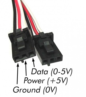
This means that if you want to know what the temperature is (or pressure, humidity, position, etc.), you will need to measure the sensor's output voltage. In order to do this, you can use any of our Phidgets with an analog input. Each Phidget with an analog input interfaces with sensors using three wires (as shown in the image above):
- Power (+5 VDC) - provides the sensor with power.
- Ground
- Data - The sensor manipulates the voltage on this line. The Phidget measures and reports this voltage.
For information about different types of analog inputs, as well as the software objects that are used with analog inputs, visit the Phidgets Connectors page. Next, we will take a look at the connector that is commonly used for our sensors.
Connector
Each analog input uses a 3-pin, 0.100 inch pitch locking connector.
Pictured here is a plug with the connections labeled.
The Phidget cables that are designed to plug into these inputs can be found here.
The connectors and pins they use are also commonly available (usually through digikey) - refer to the table below for manufacturer part numbers.
| Manufacturer
|
Part Number
|
Description
|
| Molex
|
50-57-9403
|
3 Position Cable Connector
|
| Molex
|
16-02-0102
|
Wire Crimp Insert for Cable Connector
|
| Molex
|
70543-0002
|
3 Position Vertical PCB Connector
|
| Molex
|
70553-0002
|
3 Position Right-Angle PCB Connector (Gold)
|
| Molex
|
70553-0037
|
3 Position Right-Angle PCB Connector (Tin)
|
| Molex
|
15-91-2035
|
3 Position Right-Angle PCB Connector - Surface Mount
|
Electrical Specifications
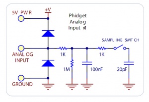
Schematic for a Phidgets analog input.
The maximum total current consumed by all analog inputs should be limited to 400mA.
The voltage measurement is represented in the software through the Voltage property as a value between 0 and 5 volts.
5V corresponds to a high sensor value, and 0V corresponds to zero sensor activity.
The analog inputs on Phidgets InterfaceKits are designed for a maximum of 5V. More than this will cause unpredictable behaviour and could damage the board.
Connecting non-Phidget devices to the Analog Inputs
Here are some circuit diagrams that illustrate how to connect various non Phidgets devices to the analog inputs on your Phidget.
Sensing the Value of a Variable Resistance Sensor
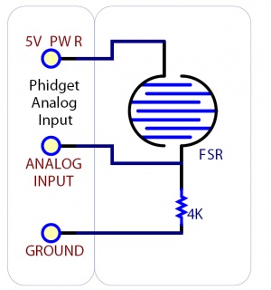
Schematic for connecting to an FSR.
In this diagram, an FSR (Force Sensitive Resistor) is shown.
Sensing the Position of a Potentiometer
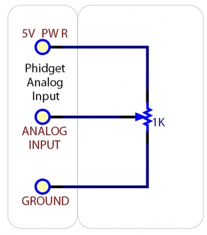
Schematic for connecting to a potentiometer
This diagram shows how to monitor the position of a potentiometer.
Interfacing to an Arbitrary Sensor
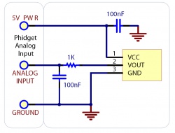
Schematic for connecting to a sensor.
Normally, you can connect a sensor directly to the analog input as long as it has a 0-5V range (or smaller). However, if the sensor is not designed to send its signal across a long cable, you may need to add components as shown in the image.
Note the use of power supply decoupling and the RC Filter on the output.
The RC filter also prevents VOUT from oscillating on many sensors.
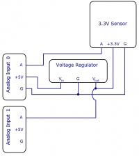
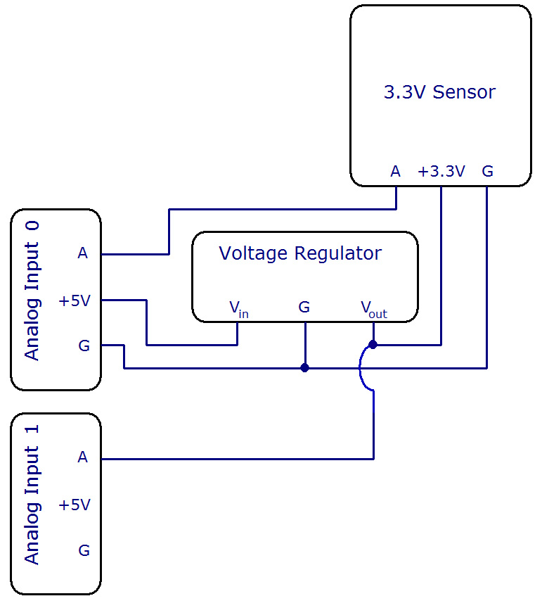
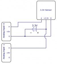
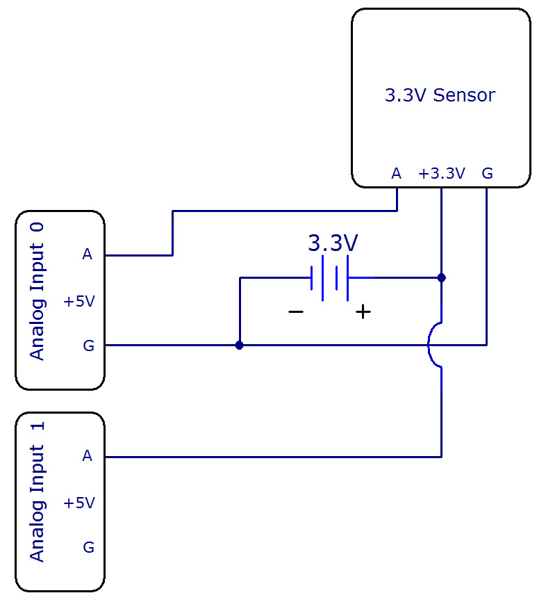
Interfacing 3.3V Sensors
When using a 3.3V sensor with the analog input of a Phidget InterfaceKit, the main challenge is generating the 3.3V supply. You can either buy a 3.3V power supply, or you can buy a voltage regulator to convert the 5V line on the analog input to a 3.3V line, as illustrated in the diagrams. You can also use a second analog input to monitor the output of the 3.3V supply on the regulator.
Factors that can affect Accuracy
- High Output Impedance - Sensors that have a high output impedance will be distorted by the input impedance of the analog input.
If your output impedance is high, it is possible to correct for this distortion to some extent in your software application.
- Voltage Drop - Phidget cables have some resistance, which can cause voltage to drop across particularly long lengths of cable. For ratiometric sensors in particular, this can affect accuracy. Long cables also potentially expose the line to a greater amount of interference from surrounding electronics.
- Intrinsic Error In Sensors - For many sensors, the error is quite predictable by testing it alongside a more accurate sensor, and can be calibrated out in software.
- Voltage Reference - Voltage Reference error. The 5.0VDC voltage reference is accurate to 0.5%.
This can be a significant source of error in some applications, but can be easily measured and compensated for.
