3052 User Guide
Required Hardware
- A 3052 Solid State Relay Phidget
- An InterfaceKit or device with a digital output
- A series electric circuit to test the relay
- Pieces of hook-up wire
- A USB Cable
- A computer
Connecting the Pieces
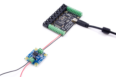
- Connect the circuit to the load terminals of the relay board.
- Connect the SSR Relay Phidget to the InterfaceKit by connecting a wire from the terminal block marked with a + to a digital output and another wire from the terminal block marked with a - to any ground terminal on the InterfaceKit.
- Connect the InterfaceKit to the computer using the USB cable.
Testing Using Windows
Phidget Control Panel
In order to demonstrate the functionality of the 1018, the Phidget Control Panel running on a Windows machine will be used.
The Phidget Control Panel is available for use on both macOS and Windows machines.
Windows
To open the Phidget Control Panel on Windows, find the ![]() icon in the taskbar. If it is not there, open up the start menu and search for Phidget Control Panel
icon in the taskbar. If it is not there, open up the start menu and search for Phidget Control Panel
macOS
To open the Phidget Control Panel on macOS, open Finder and navigate to the Phidget Control Panel in the Applications list. Double click on the ![]() icon to bring up the Phidget Control Panel.
icon to bring up the Phidget Control Panel.
For more information, take a look at the getting started guide for your operating system:
Linux users can follow the getting started with Linux guide and continue reading here for more information about the 1018.
First Look
After plugging the 1018 into your computer and opening the Phidget Control Panel, you will see something like this:
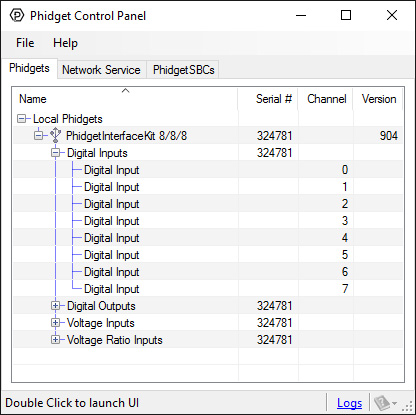
The Phidget Control Panel will list all connected Phidgets and associated objects, as well as the following information:
- Serial number: allows you to differentiate between similar Phidgets.
- Channel: allows you to differentiate between similar objects on a Phidget.
- Version number: corresponds to the firmware version your Phidget is running. If your Phidget is listed in red, your firmware is out of date. Update the firmware by double-clicking the entry.
The Phidget Control Panel can also be used to test your device. Double-clicking on an object will open an example.
Digital Output
Double-click on a Digital Output object {{{2}}} in order to run the example: [[Image:{{{1}}}_DigitalOutput_Example.jpg|center|link=]]
General information about the selected object will be displayed at the top of the window. You can also experiment with the following functionality:
- Toggle the state of the digital output by pressing the button.
Testing Using Mac OS X
- Go to the Quick Downloads section on the Mac OS X page.
- Download and run the Phidget OS X Installer
- Click on System Preferences >> Phidgets (under Other) to activate the Preference Pane
- Make sure your device is properly attached
- Double click on your device's objects in the listing to open them. The Preference Pane and examples will function very similarly to the ones described above in the Windows section.
Testing Using Linux
For a general step-by-step guide on getting Phidgets running on Linux, see the Linux page.
Using a Remote OS
We recommend testing your Phidget on a desktop OS before moving on to remote OS. Once you've tested your Phidget, you can go to the PhidgetSBC, or iOS pages to learn how to proceed.
Technical Details
Solid State Relays
Solid State Relays, or SSRs, are devices designed to operate like standard relays but without mechanical motion. Built instead out of silicon transistors, SSRs allow currents and voltages to be switched by simple digital signals from a microprocessor or any other device that can supply the small amount of current needed to activate the SSR’s internal switching mechanism. For more information on solid state relays, refer to the SSR Primer.
Protection Devices
The SSR Board is safe to use with sensitive control devices like microprocessors, and will not damage a Phidget device or your PC. Optoisolation between the control inputs and outputs of the SSR in the form of a GaAs LED paired with a set of optically-controlled MOSFETs provides protection from output to input. An on-board 47V bidirectional transorb across the relay output protects the board from static electricity and surges from inductive loads.
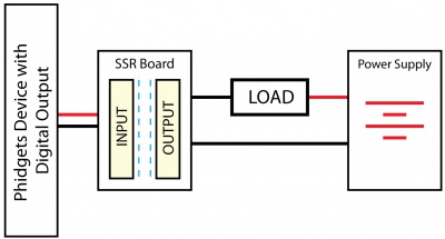
Using the SSR Board
|
Using the SSR Relay Board in your application is typically done according to the diagram on the right, though there are other implementations for it as well. |
| |
What to do Next
- Programming Languages - Find your preferred programming language here and learn how to write your own code with Phidgets!
- Phidget Programming Basics - Once you have set up Phidgets to work with your programming environment, we recommend you read our page on to learn the fundamentals of programming with Phidgets.