1102 User Guide
Getting Started
Welcome to the 1102 user guide! In order to get started, make sure you have the following hardware on hand:
- 1102 - IR Reflective Sensor 5mm
- Any Phidget with a Voltage Ratio Input port, here are some compatible products. We will be using the VINT Hub for this guide.
- USB cable and computer
- Phidget cable
Next, you will need to connect the pieces:
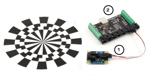
- Connect the 1102 to the 1018 with the Phidget cable.
- Connect the 1018 to your computer with the USB cable.
Now that you have everything together, let's start using the 1102!
Using the 1102
Phidget Control Panel
In order to demonstrate the functionality of the 1102, we will connect it to the 1018, and then run an example using the Phidget Control Panel on a Windows machine.
The Phidget Control Panel is available for use on both macOS and Windows machines. If you would like to follow along, first take a look at the getting started guide for your operating system:
Linux users can follow the getting started with Linux guide and continue reading here for more information about the 1102.
First Look
After plugging in the 1102 into the 1018, and the 1018 into your computer, open the Phidget Control Panel. You will see something like this:
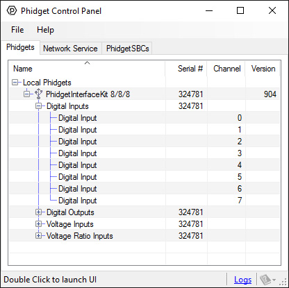
The Phidget Control Panel will list all connected Phidgets and associated objects, as well as the following information:
- Serial number: allows you to differentiate between similar Phidgets.
- Channel: allows you to differentiate between similar objects on a Phidget.
- Version number: corresponds to the firmware version your Phidget is running. If your Phidget is listed in red, your firmware is out of date. Update the firmware by double-clicking the entry.
The Phidget Control Panel can also be used to test your device. Double-clicking on an object will open an example.
Voltage Ratio Input
Double-click on a Voltage Ratio Input object in order to run the example:
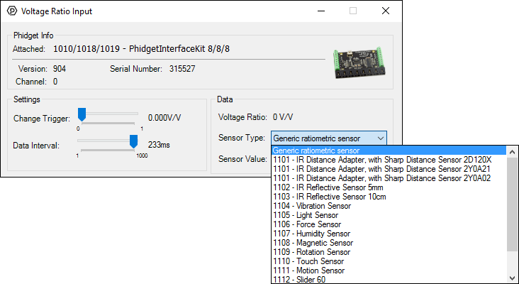
General information about the selected object will be displayed at the top of the window. You can also experiment with the following functionality:
- Modify the change trigger and/or data interval value by dragging the sliders. For more information on these settings, see the data interval/change trigger page.
- Select the 1102 from the Sensor Type drop-down menu. The example will now convert the voltage into a 1 (object detected) or 0 (no object detected) automatically. Converting the voltage to a 1 (object detected) or 0 (no object detected) is not specific to this example, it is handled by the Phidget libraries, with functions you have access to when you begin developing!
Technical Details
General
The 1102 can detect an object at 5mm. The 1102 consists of an infrared emitting diode and an NPN silicon phototransistor mounted side by side on a converging optical axis in a black plastic housing. The phototransistor responds to radiation from the emitting diode only when a reflective object passes within its field of view. The area of the optimum response approximates a circle 5mm in diameter.
The amount of reflectivity is measured by infrared and some materials that look very reflective to the human eye might not be as reflective in the infrared spectrum. The sensor can only detect objects that are between 3 to 7 mm away; it cannot see any objects outside that range.
The 1102 is not a digital sensor. The returned voltage is inversely proportional to the amount of reflectivity of the object (0V being more reflective, and 2V being less reflective), but in practice the variation between sensors is broad enough that the 1102 should not be used to measure the reflectivity of an object - only to detect if the object exists. You may have trouble using this sensor through a pane of glass, since the IR light can easily reflect off of the surface of the glass.
When working with sensors that are not digital, it is helpful to filter out noise by implementing a simple hysteresis in your code. By interpreting any voltage less than 2V as a detection, and not releasing the detection until the voltage rises above some higher threshold, such as 2.5V, multiple triggering can often be avoided.
Finally, the 1102 works best in a constrained environment, where objects can be mechanically guaranteed to be within the 3-7mm range, or not present at all.
Phidget Cable
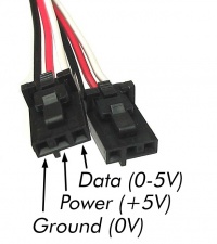
The Phidget Cable is a 3-pin, 0.100 inch pitch locking connector. Pictured here is a plug with the connections labelled. The connectors are commonly available - refer to the Analog Input Primer for manufacturer part numbers.
What to do Next
- Programming Languages - Find your preferred programming language here and learn how to write your own code with Phidgets!
- Phidget Programming Basics - Once you have set up Phidgets to work with your programming environment, we recommend you read our page on to learn the fundamentals of programming with Phidgets.