1065 User Guide: Difference between revisions
No edit summary |
No edit summary |
||
| Line 5: | Line 5: | ||
*USB cable and computer | *USB cable and computer | ||
*power supply | *power supply | ||
*DC Motor | *[{{SERVER}}/?view=comparetable&rel=DC%20Motors DC Motor] | ||
Revision as of 17:29, 21 June 2017
Getting Started
Welcome to the 1065 user guide! In order to get started, make sure you have the following hardware on hand:
- 1065 DC Motor Phidget
- USB cable and computer
- power supply
- DC Motor
Next, you will need to connect the pieces:
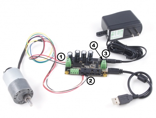
- Connect the positive wire (usually red) of the motor to the "+" terminal on the side of the Phidget opposite the USB port. Connect the negative wire (usually black) to the "-" terminal next to the red wire.
- Connect your device to your computer using the USB cable.
- Plug the DC power supply into the barrel jack, or if it doesn't have a jack, connect the loose leads to the "+" and "G" terminals between the barrel jack and USB port.
- Ensure that the DC power supply is plugged in.
Now that you have everything together, let's start using the 1065!
Using the 1065
Phidget Control Panel
In order to demonstrate the functionality of the 1065, the Phidget Control Panel running on a Windows machine will be used.
The Phidget Control Panel is available for use on both macOS and Windows machines.
Windows
To open the Phidget Control Panel on Windows, find the ![]() icon in the taskbar. If it is not there, open up the start menu and search for Phidget Control Panel
icon in the taskbar. If it is not there, open up the start menu and search for Phidget Control Panel
macOS
To open the Phidget Control Panel on macOS, open Finder and navigate to the Phidget Control Panel in the Applications list. Double click on the ![]() icon to bring up the Phidget Control Panel.
icon to bring up the Phidget Control Panel.
For more information, take a look at the getting started guide for your operating system:
Linux users can follow the getting started with Linux guide and continue reading here for more information about the 1065.
First Look
After plugging the 1065 into your computer and opening the Phidget Control Panel, you will see something like this:
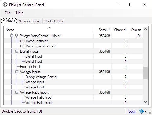
The Phidget Control Panel will list all connected Phidgets and associated objects, as well as the following information:
- Serial number: allows you to differentiate between similar Phidgets.
- Channel: allows you to differentiate between similar objects on a Phidget.
- Version number: corresponds to the firmware version your Phidget is running. If your Phidget is listed in red, your firmware is out of date. Update the firmware by double-clicking the entry.
The Phidget Control Panel can also be used to test your device. Double-clicking on an object will open an example.
DC Motor
Double-click on the DC Motor object, labelled DC Motor Controller, in order to run the example:
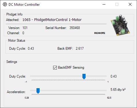
General information about the selected object will be displayed at the top of the window. You can also experiment with the following functionality:
- Toggle the BackEMF Sensing checkbox to enable/disable back-EMF sensing on the 1065.
- Drag the Target Velocity slider from -1 (full reverse) to 1 (full forward) to make the motor move.
- Manipulate the Acceleration slider to increase/decrease the amount of time it takes the DC Motor to reach a target velocity.
Encoder
Double-click on the Encoder object, labelled Encoder Input, in order to run the example:
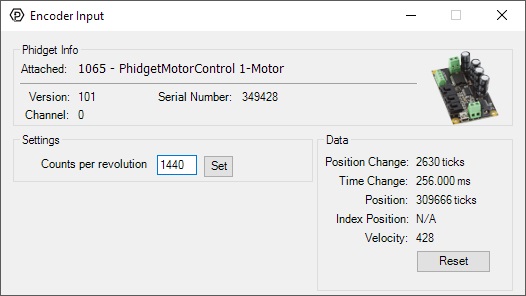
General information about the selected object will be displayed at the top of the window. You can also experiment with the following functionality:
- Position Change: the number of ticks (or quadrature cycles) that have occurred since the last change event.
- Time Change: the amount of time in milliseconds that has elapsed since the last change event.
- Position: the total position in ticks relative to where the encoder was when the window was opened.
- Index Position: the position where the index channel was last encountered. Some encoders do not support index, check your encoder's datasheet for more information.
- Velocity: the average velocity in rotations per second. A CPR must be specified to enable this functionality.
- Specify a counts per revolution (CPR) value to enable velocity calculation.
Current Input
Double-click on the Current Input object , labelled DC Motor Current Sensor, in order to run the example:
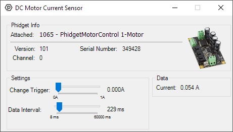
General information about the selected object will be displayed at the top of the window. You can also experiment with the following functionality:
- Modify the change trigger and/or data interval value by dragging the sliders. For more information on these settings, see the data interval/change trigger page.
Digital Input
Double-click on a Digital Input object in order to run the example:
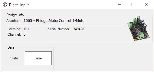
General information about the selected object will be displayed at the top of the window. You can also experiment with the following functionality:
- This is an active-low device, therefore, it will be true when connected to ground, and false when connected to a high voltage.
For more information about Digital Inputs, take a look at the Digital Input Primer
Voltage Input (Supply Voltage)
Double-click on the Voltage Input object, lablled Supply Voltage Sensor, in order to run the example:
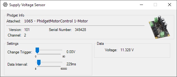
General information about the selected object will be displayed at the top of the window. You can also experiment with the following functionality:
- Modify the change trigger and/or data interval value by dragging the sliders. For more information on these settings, see the data interval/change trigger page.
Voltage Input
Double-click on a Voltage Input object in order to run the example:
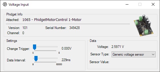
General information about the selected object will be displayed at the top of the window. You can also experiment with the following functionality:
- Modify the change trigger and/or data interval value by dragging the sliders. For more information on these settings, see the data interval/change trigger page.
- If you have an analog sensor connected that you bought from us, you can select it from the Sensor Type drop-down menu. The example will then convert the voltage into a more meaningful value based on your sensor, with units included, and display it beside the Sensor Value label. Converting voltage to a Sensor Value is not specific to this example, it is handled by the Phidget libraries, with functions you have access to when you begin developing!
For more information about Voltage Inputs, check out the Voltage Input Primer.
Voltage Ratio Input
Double-click on a Voltage Ratio Input object in order to run the example:
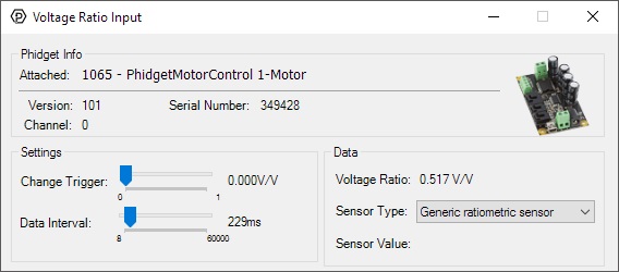
General information about the selected object will be displayed at the top of the window. You can also experiment with the following functionality:
- The voltage ratio is reported in Volts per Volt. For example, if the Phidget is providing 5V and the sensor is sending back 2.5V, the ratio will be 0.5V/V.
- Modify the change trigger and/or data interval value by dragging the sliders. For more information on these settings, see the data interval/change trigger page.
- If you have an analog sensor connected that you bought from us, you can select it from the Sensor Type drop-down menu. The example will then convert the voltage into a more meaningful value based on your sensor, with units included, and display it beside the Sensor Value label. Converting voltage to a Sensor Value is not specific to this example, it is handled by the Phidget libraries, with functions you have access to when you begin developing!
For more information about Voltage Ratio Inputs, check out the Voltage Ratio Input Primer.
Technical Details
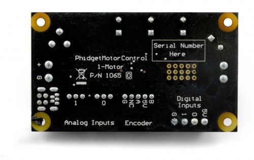
Connections
The ports and terminal blocks on this board are labelled on the underside to save space:
Further Reading
For more information on the analog inputs on the 1065, check the Analog Input Primer.
For more information about encoders, check the Encoder Primer.
For more information about DC motors and how to control them, check the DC Motor and Controller Primer.
What to do Next
- Programming Languages - Find your preferred programming language here and learn how to write your own code with Phidgets!
- Phidget Programming Basics - Once you have set up Phidgets to work with your programming environment, we recommend you read our page on to learn the fundamentals of programming with Phidgets.