1056 User Guide: Difference between revisions
| Line 65: | Line 65: | ||
Magnetic field data will become unavailable for ~28ms every 2 seconds as the compass perform internal calibrations. During this time, polling the magnetic field will return EPHIDGET_UNKNOWNVAL, or throw an UNKNOWNVAL exception. The magnetic field data in the SpatialData event will equal PUNK_DBL. | Magnetic field data will become unavailable for ~28ms every 2 seconds as the compass perform internal calibrations. During this time, polling the magnetic field will return EPHIDGET_UNKNOWNVAL, or throw an UNKNOWNVAL exception. The magnetic field data in the SpatialData event will equal PUNK_DBL. | ||
{{compasscalibration|1056}} | |||
====Further Reading==== | ====Further Reading==== | ||
Revision as of 16:16, 6 September 2013
| |
| Go to this device's product page |
Getting Started
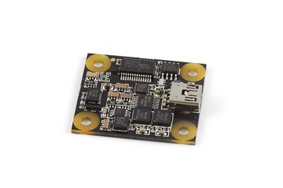
Checking the Contents
|
You should have received:
|
||
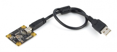
Connecting the Pieces
|
Connect the PhidgetSpatial 3/3/3 to your PC using the Mini-B USB cable. |
| |
Testing Using Windows 2000 / XP / Vista / 7
Make sure you have the current version of the Phidget library installed on your PC. If you don't, follow these steps:
- Go to the Quick Downloads section on the Windows page
- Download and run the Phidget21 Installer (32-bit, or 64-bit, depending on your system)
- You should see the
 icon on the right hand corner of the Task Bar.
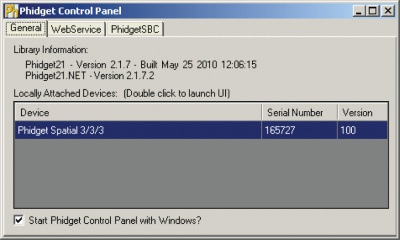
Running Phidgets Sample Program
Double clicking on the ![]() icon loads the Phidget Control Panel; we will use this program to ensure that your new Phidget works properly.
icon loads the Phidget Control Panel; we will use this program to ensure that your new Phidget works properly.
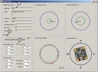
The source code for the Spatial-full sample program can be found in the quick downloads section on the C# Language Page. If you'd like to see examples in other languages, you can visit our Languages page.
Updating Device Firmware
If an entry in this list is red, it means the firmware for that device is out of date. Double click on the entry to be given the option of updating the firmware. If you choose not to update the firmware, you can still run the example for that device after refusing.
|
Double Click on the |
| |
|
|
Testing Using Mac OS X
- Go to the Quick Downloads section on the Mac OS X page
- Download and run the Phidget OS X Installer
- Click on System Preferences >> Phidgets (under Other) to activate the Preference Pane
- Make sure that the Phidget Spatial 3/3/3 is properly attached.
- Double Click on Phidget Spatial 3/3/3 in the Phidget Preference Pane to bring up the Spatial-full Sample program. This program will function in a similar way as the Windows version.
Using Linux
For a step-by-step guide on getting Phidgets running on Linux, check the Linux page.
Using Windows Mobile / CE 5.0 / CE 6.0
Technical Details
3-Axis Accelerometer
For more information on how to use the accelerometer, check the Accelerometer Primer.
3-Axis Gyroscope
For more information on the gyroscope, see the Gyroscope Primer.
3-Axis Magnetometer (Compass)
The magnetometer reports the sum of all magnetic fields acting on the 1056 device. The earth’s magnetic field is only one source that affects this measurement. In order to get accurate bearing data from the magnetometer - ie. to find magnetic north as a compass - any interfering magnetic effects need to be calibrated out. For more information about calibration, see the section below, or the Compass Primer.
Any magnetic field that is stationary with respect to the 1056 device, and less than ± 3 Gauss, can be calibrated out of the magnetic field measurement. This includes both hard and soft iron effects caused by nearby ferrous and magnetic materials. Interfering magnetic fields that vary in strength and orientation with respect to the 1056 device cannot be easily calibrated out.
Magnetic field data will become unavailable for ~28ms every 2 seconds as the compass perform internal calibrations. During this time, polling the magnetic field will return EPHIDGET_UNKNOWNVAL, or throw an UNKNOWNVAL exception. The magnetic field data in the SpatialData event will equal PUNK_DBL.
Further Reading
For more information on magnetometers (compasses), see the Compass Primer.
API
Data Structures
SpatialData {
- double acceleration[3];
- double angularRate[3];
- double magneticField[3];
- Timestamp time;
};
Timestamp {
- int seconds; -time since attach event
- int microseconds; -time since last second
};
The SpatialData Structure is used by the OnSpatialData event. This contains acceleration data, angular rate data, magnetic field data, and a timestamp. The timestamp is an accurate measurement streamed from the hardware,and can be trusted over a local software timestamp. This timestamp is generally used for integrating angular rate into a heading over time.
Properties
Functions
Events
Product History
Template:UGhist Template:UGrow Template:UGrow Template:UGrow Template:UGrow