1054 User Guide: Difference between revisions
No edit summary |
No edit summary |
||
| Line 9: | Line 9: | ||
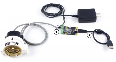
===Connecting the Pieces=== | ===Connecting the Pieces=== | ||
[[Image: | [[Image:1054_0_Connecting_The_Hardware.jpg|400px|right|link=]] | ||
# Connect your pulse output device to the Frequency Counter Phidget. Connect the power wire to 5V, the ground wire to G, and the positive and negative data lines to '+' and '-'. If there is only one data line, connect it to '+' if it's a PNP sensor, and '-' if it's NPN. | # Connect your pulse output device to the Frequency Counter Phidget. Connect the power wire to 5V, the ground wire to G, and the positive and negative data lines to '+' and '-'. If there is only one data line, connect it to '+' if it's a PNP sensor, and '-' if it's NPN. | ||
# Connect the 1054 to your computer using the USB cable. | # Connect the 1054 to your computer using the USB cable. | ||
Revision as of 20:05, 30 August 2016
Required Hardware
- A 1054 Frequency Counter Phidget
- A device with a frequency/pulse output
- A USB Cable
- A Computer
Connecting the Pieces
- Connect your pulse output device to the Frequency Counter Phidget. Connect the power wire to 5V, the ground wire to G, and the positive and negative data lines to '+' and '-'. If there is only one data line, connect it to '+' if it's a PNP sensor, and '-' if it's NPN.
- Connect the 1054 to your computer using the USB cable.
Testing Using Windows
Phidget Control Panel
In order to demonstrate the functionality of the 1054, the Phidget Control Panel running on a Windows machine will be used.
The Phidget Control Panel is available for use on both macOS and Windows machines.
Windows
To open the Phidget Control Panel on Windows, find the ![]() icon in the taskbar. If it is not there, open up the start menu and search for Phidget Control Panel
icon in the taskbar. If it is not there, open up the start menu and search for Phidget Control Panel
macOS
To open the Phidget Control Panel on macOS, open Finder and navigate to the Phidget Control Panel in the Applications list. Double click on the ![]() icon to bring up the Phidget Control Panel.
icon to bring up the Phidget Control Panel.
For more information, take a look at the getting started guide for your operating system:
Linux users can follow the getting started with Linux guide and continue reading here for more information about the 1054.
First Look
After plugging the 1054 into your computer and opening the Phidget Control Panel, you will see something like this:
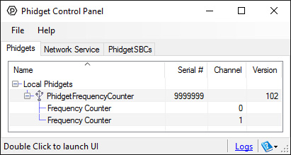
The Phidget Control Panel will list all connected Phidgets and associated objects, as well as the following information:
- Serial number: allows you to differentiate between similar Phidgets.
- Channel: allows you to differentiate between similar objects on a Phidget.
- Version number: corresponds to the firmware version your Phidget is running. If your Phidget is listed in red, your firmware is out of date. Update the firmware by double-clicking the entry.
The Phidget Control Panel can also be used to test your device. Double-clicking on an object will open an example.
Frequency Counter
Double-click on the Frequency Counter object in order to run the example: [[Image:{{{1}}}_FrequencyCounter_Example.jpg|center|link=]]
General information about the selected object will be displayed at the top of the window. You can also experiment with the following functionality:
- Frequency: the average frequency calculated from the pulses in the event so far.
- Total Count: the total number of pulses since opening the example.
- Total Time: the total time in milliseconds that has elapsed since opening this example.
- Enter a cutoff frequency in the Frequency Cutoff(Hz) textbox and the {{{1}}} will ignore frequencies below the specified value.
Testing Using Mac OS X
- Go to the Quick Downloads section on the Mac OS X page.
- Download and run the Phidget OS X Installer
- Click on System Preferences >> Phidgets (under Other) to activate the Preference Pane
- Make sure your device is properly attached
- Double click on your device's objects in the listing to open them. The Preference Pane and examples will function very similarly to the ones described above in the Windows section.
Testing Using Linux
For a general step-by-step guide on getting Phidgets running on Linux, see the Linux page.
Using a Remote OS
We recommend testing your Phidget on a desktop OS before moving on to remote OS. Once you've tested your Phidget, you can go to the PhidgetSBC, or iOS pages to learn how to proceed.
Technical Details
The PhidgetFrequencyCounter contains two channels to sense two different inputs. Each channel has two different circuits to sense for logic level-frequencies or zero-centered frequencies. The measurable frequency is accurate to 0.25% up to 1MHz. The Frequency Counter may measure frequencies past 1 Mhz, but the input voltage specifications will not hold. The PhidgetFrequencyCounter can measure frequencies down to ~ 0.01Hz. However the response time of these measurements is directly related to the frequency, thus it could take 1 or 2 periods(100-200s) to detect the input frequency.
Logic-Level Frequencies
The logic-level sensing circuit has a hysteresis range from 0.9V to 2.4V. This will allow the circuit to count both 3.3V and 5V logic levels. In addition to logic-level signals, this will also accept the pulses from sensors with open collector outputs. When the input signals are either 3.3V or 5V, the maximum sensed frequency is 1.5Mhz. Most digital sensors that are powered from a signal positive power supply will output a logic-level frequency.
Zero-Centered Frequencies
The zero-centered sensing circuit can be used for input signals where you want to count as it crosses zero volts. A hysteresis of 30mVpp filters noise. At maximum frequency (1Mhz), a signal of 400mVPP is required for reliable counting. A common application that uses a zero centered frequency output is a simple magnetic tachometer, which produces a sine wave around 0 volts.
Differential Inputs
The PhidgetFrequencyCounter uses differential inputs - that is, the voltage being compared is the difference between the (+) and (-) inputs. If your application has a slightly different ground from your USB ground, the common mode rejection in the 1054 will handle small differences in ground. For many applications, the signal being measured is single ended - that is, your sensor outputs only one signal, and you can directly connect the ground of the sensor to the ground of the 1054. In this case, ensure the (-) input is tied to ground. Never allow either input to be left unconnected.
Output Voltage
USB Voltage is passed directly to the +5V terminal on the green blocks.
What to do Next
- Programming Languages - Find your preferred programming language here and learn how to write your own code with Phidgets!
- Phidget Programming Basics - Once you have set up Phidgets to work with your programming environment, we recommend you read our page on to learn the fundamentals of programming with Phidgets.