1051 User Guide: Difference between revisions
No edit summary |
No edit summary |
||
| Line 9: | Line 9: | ||
===Connecting the Pieces=== | ===Connecting the Pieces=== | ||
[[Image: | [[Image:1051_1_Connecting_The_Hardware.jpg|400px|right|link=]] | ||
# Connect the thermocouple to the inputs on the Phidget TemperatureSensor. The datasheet or product page for the thermocouple should tell you which wire is positive and which is negative. | # Connect the thermocouple to the inputs on the Phidget TemperatureSensor. The datasheet or product page for the thermocouple should tell you which wire is positive and which is negative. | ||
# Connect the Phidget to your computer using the USB cable. | # Connect the Phidget to your computer using the USB cable. | ||
Revision as of 20:46, 30 August 2016
Required Hardware
- A 1051 Phidget TemperatureSensor 1-Input
- A Thermocouple
- A USB Cable
- A computer
Connecting the Pieces
- Connect the thermocouple to the inputs on the Phidget TemperatureSensor. The datasheet or product page for the thermocouple should tell you which wire is positive and which is negative.
- Connect the Phidget to your computer using the USB cable.
Testing Using Windows
Phidget Control Panel
In order to demonstrate the functionality of the 1051, the Phidget Control Panel running on a Windows machine will be used.
The Phidget Control Panel is available for use on both macOS and Windows machines.
Windows
To open the Phidget Control Panel on Windows, find the ![]() icon in the taskbar. If it is not there, open up the start menu and search for Phidget Control Panel
icon in the taskbar. If it is not there, open up the start menu and search for Phidget Control Panel
macOS
To open the Phidget Control Panel on macOS, open Finder and navigate to the Phidget Control Panel in the Applications list. Double click on the ![]() icon to bring up the Phidget Control Panel.
icon to bring up the Phidget Control Panel.
For more information, take a look at the getting started guide for your operating system:
Linux users can follow the getting started with Linux guide and continue reading here for more information about the 1051.
First Look
After plugging the 1051 into your computer and opening the Phidget Control Panel, you will see something like this:
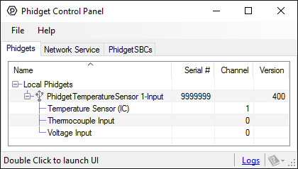
The Phidget Control Panel will list all connected Phidgets and associated objects, as well as the following information:
- Serial number: allows you to differentiate between similar Phidgets.
- Channel: allows you to differentiate between similar objects on a Phidget.
- Version number: corresponds to the firmware version your Phidget is running. If your Phidget is listed in red, your firmware is out of date. Update the firmware by double-clicking the entry.
The Phidget Control Panel can also be used to test your device. Double-clicking on an object will open an example.
Temperature Sensor (Thermocouple)
Double-click on the Temperature Sensor object, labelled Thermocouple Input, in order to run the example: [[Image:{{{1}}}_TemperatureSensorThermocouple_Example.jpg|center|link=]]
General information about the selected object will be displayed at the top of the window. You can also experiment with the following functionality:
- Modify the change trigger and/or data interval value by dragging the sliders. For more information on these settings, see the data interval/change trigger page.
- Select your thermocouple type from the Thermocouple Type drop-down menu.
- The measured temperature will be updated next to the Temperature label. Touch the thermocouple wire with your hands to see the temperature increase. If the temperature decreases when it should be increasing, you may have the wires plugged in incorrectly.
Temperature Sensor {{{3}}}
Double-click on the Temperature Sensor object {{{2}}} in order to run the example: [[Image:{{{1}}}_TemperatureSensorIC_Example.jpg|center|link=]]
General information about the selected object will be displayed at the top of the window. You can also experiment with the following functionality:
- Modify the change trigger and/or data interval value by dragging the sliders. For more information on these settings, see the data interval/change trigger page.
- The measured temperature can be seen next to the Temperature label. Cover the board with your hands to see the temperature quickly rise.
Voltage Input
Double-click on the Voltage Input object {{{2}}} in order to run the example: [[Image:{{{1}}}_VoltageInput_Example.jpg|center|link=]]
General information about the selected object will be displayed at the top of the window. You can also experiment with the following functionality:
- Modify the change trigger and/or data interval value by dragging the sliders. For more information on these settings, see the data interval/change trigger page.
Testing Using Mac OS X
- Go to the Quick Downloads section on the Mac OS X page.
- Download and run the Phidget OS X Installer
- Click on System Preferences >> Phidgets (under Other) to activate the Preference Pane
- Make sure your device is properly attached
- Double click on your device's objects in the listing to open them. The Preference Pane and examples will function very similarly to the ones described above in the Windows section.
Testing Using Linux
For a general step-by-step guide on getting Phidgets running on Linux, see the Linux page.
Using a Remote OS
We recommend testing your Phidget on a desktop OS before moving on to remote OS. Once you've tested your Phidget, you can go to the PhidgetSBC, or iOS pages to learn how to proceed.
Technical Details
Cold Junction Compensation and Self-heating
Thermocouples consist of two junctions, one where the thermocouple meets the Phidget and one where the two wires are welded together at the sensing end of the device. In simplified terms, a thermocouple works by detecting the temperature difference between these two junctions. As such, in order to measure the temperature at the sensing end we need to know the temperature where the thermocouple connects to the Phidget. To do so, there is an ambient temperature sensor on the board.
An important thing to note is that the ambient temperature sensor measures the temperature of the board and the air around it, though not specifically at the junction. Generally you can assume they are nearly the same temperature, however as the electronics heat up by being powered on there can be some small error introduced. This is exacerbated by having the board in an enclosed space where normal airflow is restricted thereby increasing the effect of self-heating. As a result we recommend that the board be left in as open and well ventilated/cooled a place as possible to minimize this error source.
For more information on thermocouples, check out the Thermocouple Primer.
What to do Next
- Programming Languages - Find your preferred programming language here and learn how to write your own code with Phidgets!
- Phidget Programming Basics - Once you have set up Phidgets to work with your programming environment, we recommend you read our page on to learn the fundamentals of programming with Phidgets.
Product History
Template:UGhist Template:UGrow2 Template:UGrow2 Template:UGrow2 Template:UGrow2 Template:UGrow2 Template:UGrow2 Template:UGrow2