1047 User Guide: Difference between revisions
No edit summary |
No edit summary |
||
| (18 intermediate revisions by 4 users not shown) | |||
| Line 1: | Line 1: | ||
__NOINDEX__ | |||
<metadesc>The PhidgetEncoder HighSpeed 4-Input reads up to four encoders simultaneously. Includes 4 digital inputs for reading limit switches.</metadesc> | |||
[[Category:UserGuide]] | [[Category:UserGuide]] | ||
==Getting Started== | ==Getting Started== | ||
{{UGIntro|1047}} | |||
*[{{SERVER}}/products.php?product_id=1047 1047 Encoder Phidget] | |||
*USB cable and computer | |||
*{{CT|Encoder|Encoder}} | |||
Next, you will need to connect the pieces: | |||
[[Image:1047_0_Connecting_The_Hardware.jpg|500px|right|link=]] | |||
# Connect the encoder to the | # Connect the encoder to the 1047 Encoder Phidget using one of the included encoder cables (Soldering may be required). | ||
# Connect | # Connect your device to your computer using the USB cable. | ||
= | <br clear="all"> | ||
{{UGIntroDone|1047}} | |||
{{ | ==Using the 1047== | ||
{{UGcontrolpanel|1047}} | |||
{{UGEncoderENABLE|1047}} | |||
{{ | {{ugDigitalInput|1047|{{UGDigitalInputActiveLow}}}} | ||
{{ | {{ugAddressingInformation}} | ||
}} | |||
{{ugUsingYourOwnProgram|1047}} | |||
==Technical Details== | |||
===General=== | |||
=== | The 1047 can be used with a wide assortment of mechanical and optical encoders. The encoder should be of quadrature output type, indicating that there will be two quadrature output channels (usually labeled A and B) and a third output channel (only on some encoders) to signal when the index pin (a reference point for zero position or a complete revolution) has been reached. | ||
The 1047 is able to read four encoders simultaneously. Encoders are not powered up until all initialization of the device is complete. It is possible to enable some or all encoders, depending on how many of the channels are being used. This can also be used to reduce power consumption when certain encoders are not needed. | |||
The 1047 has the added ability to time the duration between a group of quadrature changes. The time is returned in microseconds. This time value can be used to calculate velocity and acceleration with very high precision. | |||
If the number of quadrature counts per revolution is unknown for a particular encoder, this value can be determined by using the index signal. In addition, it is possible to monitor how many counts have occurred since the last index. The index signal is an output only on certain encoders. Refer to the encoder’s description to check if this third output channel exists or not. If the encoder does not have this signal, it is still possible to use it with the 1046, but an event for the index will never get triggered. | |||
The maximum rate of the 1046 is specified at 250,000 quadrature cycles per second. Since this device counts pulses rather than cycles, you could also say that it counts a maximum of 1,000,000 pulses per second (since there are four pulses in a cycle). In your application, these numbers relate directly to the number of revolutions per second you wish to measure, and the number of counts per revolution specified for your encoder. If your encoder's wheel has 1000 counts per revolution, then the limit on measurable revolutions per second is 250, or 15,000 rpm (which, for the 1047, corresponds to 1000 position changes in software per second). | |||
One of the most common problems encountered with connecting encoders to a 1047 is a strange | One of the most common problems encountered with connecting encoders to a 1047 is a strange ''jitter'' characterized by the encoder position appearing to switch back and forth between 0 and 1 or -1 and nothing else. This is usually indicative of a bad connection on either the A or B channel. You should check that the wiring is sound and try again. | ||
===Choosing Encoders=== | ===Choosing Encoders=== | ||
The | The 1046 incorporates a 10 kOhm pull-up resistor on each line from the encoder input connector. If your encoder is mechanical, these pull-up resistors eliminate the requirement to add your own external pull-up resistors. | ||
Some optical encoders will have a simple photo-transistor/open-collector output. The 10 kOhm pull-up resistor may have to be augmented with a stronger parallel resistor if your optical encoder datasheet calls for it. Some open-collector outputs will not be strong enough to pull this resistor to ground. These encoders are not compatible with the 1047, and may only work initially, or not at all. If you have any doubts, please contact us. | |||
Most optical encoders have a push-pull output, and the pull-up resistor is irrelevant, but weak enough not cause problems. | Most optical encoders have a push-pull output, and the pull-up resistor is irrelevant, but weak enough not cause problems. | ||
We have reviewed the following encoders, and found that they can be used with the PhidgetEncoder Highspeed 4-Input. This is not meant to be a comprehensive list but should be used as examples of the type of encoders that can be used with the 1047. | We have reviewed the following encoders, and found that they can be used with the PhidgetEncoder Highspeed 4-Input. This is not meant to be a comprehensive list but should be used as examples of the type of encoders that can be used with the 1047. | ||
{| style=" | {|class = "wikitable" | ||
| align="center" style="background:#f0f0f0;"|'''Manufacturer ''' | |||
| align="center" style="background:#f0f0f0;"|'''Web Page''' | |||
| align="center" style="background:#f0f0f0;"|'''Part Number''' | |||
|- | |- | ||
| | |align=center| Grayhill | ||
| | |align=center| [http://www.Grayhill.com www.Grayhill.com] | ||
| | |align=center| Series 63R, Series 61R Series 63Q TTL Output | ||
|- | |- | ||
| | |align=center| US Digital (Recommended) | ||
| | |align=center| [http://www.USDigital.com www.USDigital.com] | ||
| | |align=center| S4, S5, E2, E3, E4, E4P, etc. | ||
|- | |- | ||
| | |align=center| Avago Technologies (Formerly Agilent) | ||
| | |align=center| [http://www.avagotech.com www.avagotech.com] | ||
| | |align=center| HEDS 5500 | ||
|- | |- | ||
| | |align=center| CUI Inc. | ||
| | |align=center| [http://www.cui.com www.cui.com] | ||
| | |align=center| AMT103-V | ||
|- | |- | ||
|} | |} | ||
| Line 113: | Line 86: | ||
{| style=" | {|class = "wikitable" | ||
| align="center" style="background:#f0f0f0;"|'''Manufacturer ''' | |||
| align="center" style="background:#f0f0f0;"|'''Part Number''' | |||
| align="center" style="background:#f0f0f0;"|'''Description''' | |||
|- | |- | ||
| | |align=center| Molex | ||
| | |align=center| 50-57-9405 | ||
| | |align=center| 5 Position Cable Connector | ||
|- | |- | ||
| | |align=center| Molex | ||
| | |align=center| 16-02-0102 | ||
| | |align=center| Wire Crimp Insert for Cable Connector | ||
|- | |- | ||
| | |align=center| Molex | ||
| | |align=center| 70543-0004 | ||
| | |align=center| 5 Position Vertical PCB Connector | ||
|- | |- | ||
| | |align=center| Molex | ||
| | |align=center| 70553-0004 | ||
| | |align=center| 5 Position Right-Angle PCB Connector (Gold) | ||
|- | |- | ||
| | |align=center| Molex | ||
| | |align=center| 70553-0039 | ||
| | |align=center| 5 Position Right-Angle PCB Connector (Tin) | ||
|- | |- | ||
| | |align=center| Molex | ||
| | |align=center| 15-91-2055 | ||
| | |align=center| 5 Position Right-Angle PCB Connector - Surface Mount | ||
|- | |- | ||
|} | |} | ||
| Line 147: | Line 121: | ||
===Further Reading=== | ===Further Reading=== | ||
If you want to know more about encoders, check out the [[Encoder Primer]]. If you'd like to know more about the digital inputs on the 1047, visit the [[Digital Input Primer]]. | |||
{{UGnext|}} | |||
{{ | |||
Revision as of 16:11, 17 October 2019
Getting Started
Welcome to the 1047 user guide! In order to get started, make sure you have the following hardware on hand:
- 1047 Encoder Phidget
- USB cable and computer
- Encoder
Next, you will need to connect the pieces:
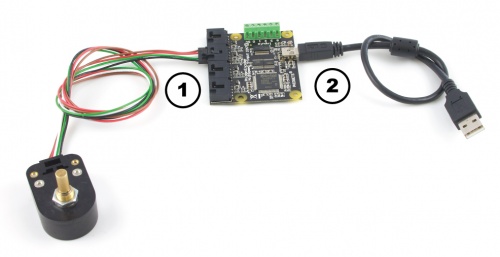
- Connect the encoder to the 1047 Encoder Phidget using one of the included encoder cables (Soldering may be required).
- Connect your device to your computer using the USB cable.
Now that you have everything together, let's start using the 1047!
Using the 1047
Phidget Control Panel
In order to demonstrate the functionality of the 1047, the Phidget Control Panel running on a Windows machine will be used.
The Phidget Control Panel is available for use on both macOS and Windows machines.
Windows
To open the Phidget Control Panel on Windows, find the ![]() icon in the taskbar. If it is not there, open up the start menu and search for Phidget Control Panel
icon in the taskbar. If it is not there, open up the start menu and search for Phidget Control Panel
macOS
To open the Phidget Control Panel on macOS, open Finder and navigate to the Phidget Control Panel in the Applications list. Double click on the ![]() icon to bring up the Phidget Control Panel.
icon to bring up the Phidget Control Panel.
For more information, take a look at the getting started guide for your operating system:
Linux users can follow the getting started with Linux guide and continue reading here for more information about the 1047.
First Look
After plugging the 1047 into your computer and opening the Phidget Control Panel, you will see something like this:
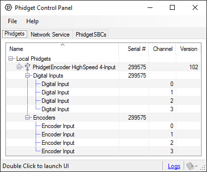
The Phidget Control Panel will list all connected Phidgets and associated objects, as well as the following information:
- Serial number: allows you to differentiate between similar Phidgets.
- Channel: allows you to differentiate between similar objects on a Phidget.
- Version number: corresponds to the firmware version your Phidget is running. If your Phidget is listed in red, your firmware is out of date. Update the firmware by double-clicking the entry.
The Phidget Control Panel can also be used to test your device. Double-clicking on an object will open an example.
Encoder
Double-click on the Encoder object, labelled Encoder Input, in order to run the example:
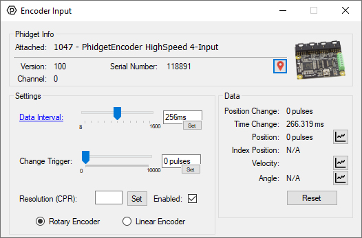
General information about the selected object will be displayed at the top of the window. You can also experiment with the following functionality:
- Toggle the Enabled checkbox to enable/disable the 1047.
- Specify a counts per revolution (CPR) value to enable velocity calculation.
- Position Change: the number of ticks (or quadrature cycles) that have occurred since the last change event.
- Time Change: the amount of time in milliseconds that has elapsed since the last change event.
- Position: the total position in ticks relative to where the encoder was when the window was opened.
- Index Position: the position where the index channel was last encountered. Some encoders do not support index, check your encoder's datasheet for more information.
- Velocity: the average velocity in rotations per second. A CPR must be specified to enable this functionality.
Digital Input
Double-click on a Digital Input object in order to run the example:
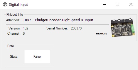
General information about the selected object will be displayed at the top of the window. You can also experiment with the following functionality:
- This is an active-low device, therefore, it will be true when connected to ground, and false when connected to a high voltage.
For more information about Digital Inputs, take a look at the Digital Input Primer
Finding The Addressing Information
Before you can access the device in your own code, and from our examples, you'll need to take note of the addressing parameters for your Phidget. These will indicate how the Phidget is physically connected to your application. For simplicity, these parameters can be found by clicking the button at the top of the Control Panel example for that Phidget.

In the Addressing Information window, the section above the line displays information you will need to connect to your Phidget from any application. In particular, note the Channel Class field as this will be the API you will need to use with your Phidget, and the type of example you should use to get started with it. The section below the line provides information about the network the Phidget is connected on if it is attached remotely. Keep track of these parameters moving forward, as you will need them once you start running our examples or your own code.

Using Your Own Program
You are now ready to start writing your own code for the device. The best way to do that is to start from our Code Samples.
Select your programming language of choice from the drop-down list to get an example for your device. You can use the options provided to further customize the example to best suit your needs.
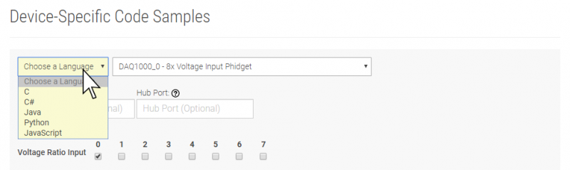
Once you have your example, you will need to follow the instructions on the page for your programming language to get it running. To find these instructions, select your programming language from the Programming Languages page.
Technical Details
General
The 1047 can be used with a wide assortment of mechanical and optical encoders. The encoder should be of quadrature output type, indicating that there will be two quadrature output channels (usually labeled A and B) and a third output channel (only on some encoders) to signal when the index pin (a reference point for zero position or a complete revolution) has been reached.
The 1047 is able to read four encoders simultaneously. Encoders are not powered up until all initialization of the device is complete. It is possible to enable some or all encoders, depending on how many of the channels are being used. This can also be used to reduce power consumption when certain encoders are not needed.
The 1047 has the added ability to time the duration between a group of quadrature changes. The time is returned in microseconds. This time value can be used to calculate velocity and acceleration with very high precision.
If the number of quadrature counts per revolution is unknown for a particular encoder, this value can be determined by using the index signal. In addition, it is possible to monitor how many counts have occurred since the last index. The index signal is an output only on certain encoders. Refer to the encoder’s description to check if this third output channel exists or not. If the encoder does not have this signal, it is still possible to use it with the 1046, but an event for the index will never get triggered.
The maximum rate of the 1046 is specified at 250,000 quadrature cycles per second. Since this device counts pulses rather than cycles, you could also say that it counts a maximum of 1,000,000 pulses per second (since there are four pulses in a cycle). In your application, these numbers relate directly to the number of revolutions per second you wish to measure, and the number of counts per revolution specified for your encoder. If your encoder's wheel has 1000 counts per revolution, then the limit on measurable revolutions per second is 250, or 15,000 rpm (which, for the 1047, corresponds to 1000 position changes in software per second).
One of the most common problems encountered with connecting encoders to a 1047 is a strange jitter characterized by the encoder position appearing to switch back and forth between 0 and 1 or -1 and nothing else. This is usually indicative of a bad connection on either the A or B channel. You should check that the wiring is sound and try again.
Choosing Encoders
The 1046 incorporates a 10 kOhm pull-up resistor on each line from the encoder input connector. If your encoder is mechanical, these pull-up resistors eliminate the requirement to add your own external pull-up resistors.
Some optical encoders will have a simple photo-transistor/open-collector output. The 10 kOhm pull-up resistor may have to be augmented with a stronger parallel resistor if your optical encoder datasheet calls for it. Some open-collector outputs will not be strong enough to pull this resistor to ground. These encoders are not compatible with the 1047, and may only work initially, or not at all. If you have any doubts, please contact us.
Most optical encoders have a push-pull output, and the pull-up resistor is irrelevant, but weak enough not cause problems.
We have reviewed the following encoders, and found that they can be used with the PhidgetEncoder Highspeed 4-Input. This is not meant to be a comprehensive list but should be used as examples of the type of encoders that can be used with the 1047.
| Manufacturer | Web Page | Part Number |
| Grayhill | www.Grayhill.com | Series 63R, Series 61R Series 63Q TTL Output |
| US Digital (Recommended) | www.USDigital.com | S4, S5, E2, E3, E4, E4P, etc. |
| Avago Technologies (Formerly Agilent) | www.avagotech.com | HEDS 5500 |
| CUI Inc. | www.cui.com | AMT103-V |
Connectors
Each Input uses a 5-pin, 0.100 inch pitch locking connector. The connectors are commonly available - refer to the Table below for manufacturer part numbers.
| Manufacturer | Part Number | Description |
| Molex | 50-57-9405 | 5 Position Cable Connector |
| Molex | 16-02-0102 | Wire Crimp Insert for Cable Connector |
| Molex | 70543-0004 | 5 Position Vertical PCB Connector |
| Molex | 70553-0004 | 5 Position Right-Angle PCB Connector (Gold) |
| Molex | 70553-0039 | 5 Position Right-Angle PCB Connector (Tin) |
| Molex | 15-91-2055 | 5 Position Right-Angle PCB Connector - Surface Mount |
Note: Most of the above components can be bought at Digikey.
Further Reading
If you want to know more about encoders, check out the Encoder Primer. If you'd like to know more about the digital inputs on the 1047, visit the Digital Input Primer.
What to do Next
- Programming Languages - Find your preferred programming language here and learn how to write your own code with Phidgets!
- Phidget Programming Basics - Once you have set up Phidgets to work with your programming environment, we recommend you read our page on to learn the fundamentals of programming with Phidgets.