1046 User Guide
| |
| Go to this device's product page |
Getting Started
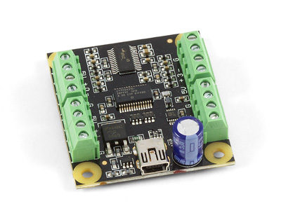
Checking the Contents
|
You should have received:
|
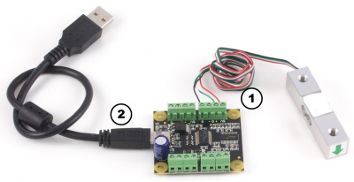
In order to test your new Phidget you will also need:
| |
Connecting the Pieces
|
| |
Testing Using Windows 2000 / XP / Vista / 7
Make sure you have the current version of the Phidget library installed on your PC. If you don't, follow these steps:
- Go to the Quick Downloads section on the Windows page
- Download and run the Phidget21 Installer (32-bit, or 64-bit, depending on your system)
- You should see the
 icon on the right hand corner of the Task Bar.
Running Phidgets Sample Program
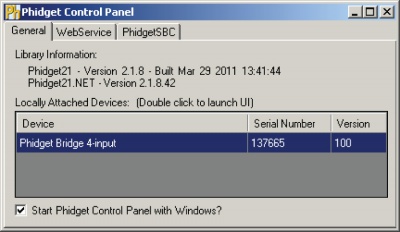
Double clicking on the ![]() icon loads the Phidget Control Panel; we will use this program to ensure that your new Phidget works properly.
icon loads the Phidget Control Panel; we will use this program to ensure that your new Phidget works properly.
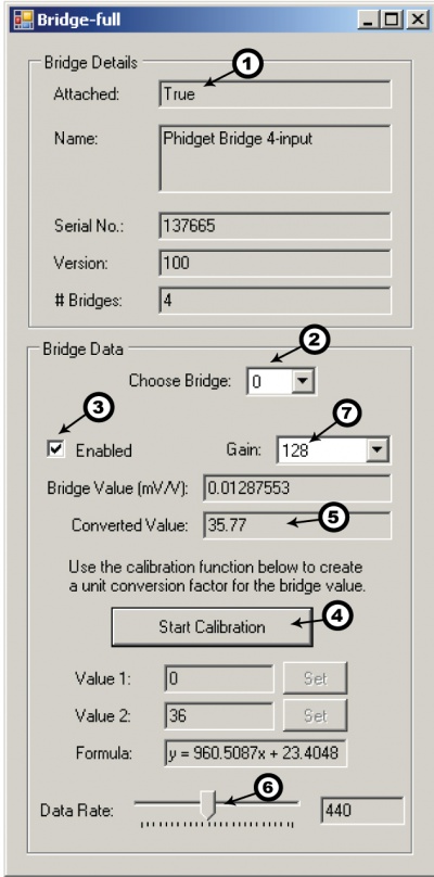
The source code for the Bridge-full sample program can be found in the quick downloads section on the C# Language Page. If you'd like to see examples in other languages, you can visit our Languages page.
Updating Device Firmware
If an entry in this list is red, it means the firmware for that device is out of date. Double click on the entry to be given the option of updating the firmware. If you choose not to update the firmware, you can still run the example for that device after refusing.
|
Double Click on the |
| |
|
|
Testing Using Mac OS X
- Go to the Quick Downloads section on the Mac OS X page
- Download and run the Phidget OS X Installer
- Click on System Preferences >> Phidgets (under Other) to activate the Preference Pane
- Make sure that the PhidgetBridge 4-input is properly attached.
- Double Click on PhidgetBridge 4-input in the Phidget Preference Pane to bring up the Bridge-full Sample program. This program will function in a similar way as the Windows version.
Using Linux
For a step-by-step guide on getting Phidgets running on Linux, check the Linux page.
Using Windows Mobile / CE 5.0 / CE 6.0
Technical Details
How to Calibrate the Bridge
We have observed a 1.5% difference between gain=1 and gain=8. This may require that each system (PhidgetBridge + sensors) are calibrated as a whole. For maximum accuracy, decide on and keep with a chosen gain before calibrating the system.
Expensive sensors will ship with a certificate of calibration specifying, often in mv/V, how the sensor responds to stimulus. Less expensive will have to be calibrated, which requires having at least two points where you know accurately what is being measured. In the case of weight measurement, this would be a known force or weight.
Record the output from the PhidgetBridge at one known point, and at a second known point. It helps if the two values are reasonably far apart. Use the values to make a linear equation to convert the PhidgetBridge output in mV/V (called X) to the appropriate unit you are measuring (called Y). Two calibration coefficients (a,b) set the slope and offset for the calibration: (Y = aX + b). It’s possible to use more than two points, if available.
The C# Bridge-full example shows how to do a 2-point calibration and apply the coefficients programmatically.
Gain Setting vs. Resolution
We report the measured voltage in a ratiometric unit known as mv/V. This is how the maximum range of sensors that use strain gauges is usually specified. mV/V is the output value in mV of the measured sensor, scaled for a 1V sensor supply voltage. This value will correspond to the physical quantity that the sensor is measuring, regardless of the actual voltage supplied to the sensor.
| Gain | Resolution | Range |
|---|---|---|
| 1 | 119 nV/V | ± 1000 mV/V |
| 8 | 14.9 nV/V | ± 125 mV/V |
| 16 | 7.45 nV/V | ± 62.5 mV/V |
| 32 | 3.72 nV/V | ± 31.25 mV/V |
| 64 | 1.86 nV/V | ± 15.625 mV/V |
| 128 | 0.93 nV/V | ± 7.8125 mV/V |
When choosing the Gain setting, it’s best to use the highest gain possible that can still measure the full range of your sensor. For an individual unit, you can apply the maximum stimulus to the sensor, and ensure the BridgeValue reported is well within the range for the Gain setting you have chosen. If many units are being deployed, it’s best to consult the data sheet for the strain gauge and look for maximum offset.
Some wheatstone bridges - most often those produced from silicon and used in pressure sensors, will have a very wide offset, and large manufacturing variation in the offset. This will restrict the gain to lower settings, particularly if the application must support a number of deployed systems with the expected variation. Fortunately, the very high precision electronics used in the PhidgetBridge means that in many application, higher gain is not necessary to get adequate accuracy and resolution.
Connecting your Strain Gauge/Load Cell
If no documentation is available for your strain gauge, it’s possible to use a multimeter to determine how to connect it, provided there are no electronics in the sensor. First, measure resistance between the 4 wires. There are 6 combinations - two combinations will have a resistance 20-40% higher than the other four. Choose one of these high-resistance combinations, and wire it into 5V and G on the PhidgetBridge. Connect the other two wires into +/-. Apply a load - if the mV/V responds in the opposite way to your expectations, flip the +/- wires.
Measurement Considerations
The PhidgetBridge is designed to measure voltages as a ratio of the supply voltage - it’s not practical to make measurements of absolute voltages with this product.
For maximum accuracy, all wires from the PhidgetBridge to the sensor should be the same length and thickness. Changes in temperature will change the resistance of the wires - if they are all the same, the errors will cancel out.
Each bridge input can be powered down, reducing power consumption with Bridge-Sensors, and useful for reducing heating of sensors, which can introduce errors.
Changing the Data Rate
Using a slower sampling rate will reduce the noise in the measurements dramatically. The noise figures are specific to individual applications and sensors. The lowest noise level achievable is 5nV/V RMS.