1044 User Guide: Difference between revisions
No edit summary |
No edit summary |
||
| Line 17: | Line 17: | ||
{{UGcontrolpanel|1044}} | {{UGcontrolpanel|1044}} | ||
{{ugAccelerometer|1044}} | {{ugAccelerometer|1044|}} | ||
{{ugGyroscope|1044}} | {{ugGyroscope|1044}} | ||
| Line 28: | Line 28: | ||
==Technical Details== | ==Technical Details== | ||
===High Resolution Mode=== | ===High Resolution Mode=== | ||
When the | When the 1044 measures an acceleration value with magnitude less than 2g, it will acquire its data from a higher precision accelerometer chip. For these measurements, the average white noise on each axis will be reduced by approximately a factor of ten, and the resolution will increase from 976 μg to 76 μg. Likewise, when the gyroscope measures a rotation value with magnitude less than 300 °/s on the Z-axis or 400 °/s on the X or Y-axis, the noise per axis will be approximately six times lower, and the resolution will increase from 0.07 °/s to 0.02 °/s. | ||
The transition from normal to high precision or vice-versa is seamless, with no additional code or equations needed. | The transition from normal to high precision or vice-versa is seamless, with no additional code or equations needed. | ||
Revision as of 17:10, 21 June 2017
Getting Started
Welcome to the 1044 user guide! In order to get started, make sure you have the following hardware on hand:
- 1044 Spatial Phidget
- USB cable and computer
Next, you will need to connect the pieces:
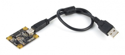
- Connect your device to your computer using the USB cable.
Now that you have everything together, let's start using the 1044!
Using the 1044
Phidget Control Panel
In order to demonstrate the functionality of the 1044, the Phidget Control Panel running on a Windows machine will be used.
The Phidget Control Panel is available for use on both macOS and Windows machines.
Windows
To open the Phidget Control Panel on Windows, find the ![]() icon in the taskbar. If it is not there, open up the start menu and search for Phidget Control Panel
icon in the taskbar. If it is not there, open up the start menu and search for Phidget Control Panel
macOS
To open the Phidget Control Panel on macOS, open Finder and navigate to the Phidget Control Panel in the Applications list. Double click on the ![]() icon to bring up the Phidget Control Panel.
icon to bring up the Phidget Control Panel.
For more information, take a look at the getting started guide for your operating system:
Linux users can follow the getting started with Linux guide and continue reading here for more information about the 1044.
First Look
After plugging the 1044 into your computer and opening the Phidget Control Panel, you will see something like this:
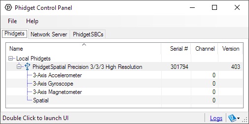
The Phidget Control Panel will list all connected Phidgets and associated objects, as well as the following information:
- Serial number: allows you to differentiate between similar Phidgets.
- Channel: allows you to differentiate between similar objects on a Phidget.
- Version number: corresponds to the firmware version your Phidget is running. If your Phidget is listed in red, your firmware is out of date. Update the firmware by double-clicking the entry.
The Phidget Control Panel can also be used to test your device. Double-clicking on an object will open an example.
Accelerometer
Double-click on the Accelerometer object in order to run the example:
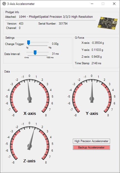
General information about the selected object will be displayed at the top of the window. You can also experiment with the following functionality:
- Modify the change trigger and/or data interval value by dragging the sliders. For more information on these settings, see the data interval/change trigger page.
- The measured values reported in g-force can be seen via labels as well as graphical dials. Try tilting the 1044 in different directions to see the labels and graphics change.
- An extremely accurate timestamp is also reported with the g-force values.
Gyroscope
Double-click on the Gyroscope object in order to run the example:
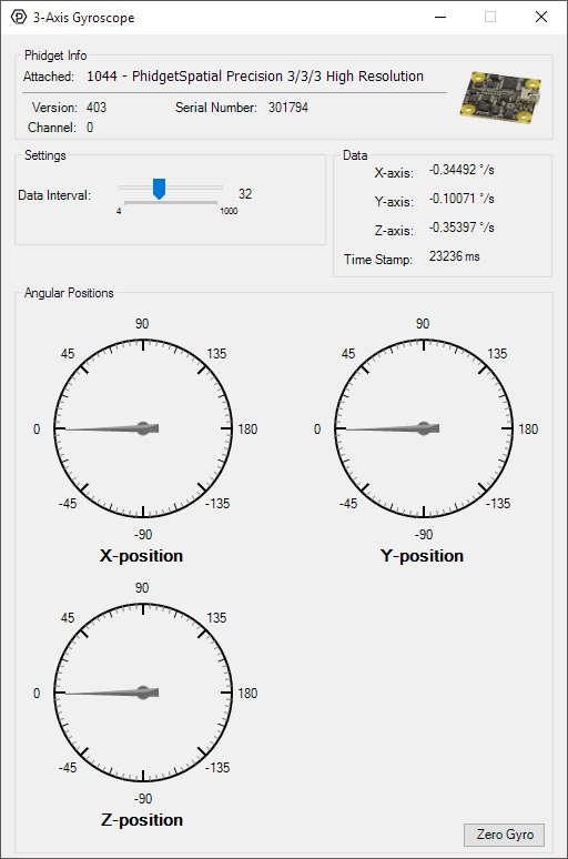
General information about the selected object will be displayed at the top of the window. You can also experiment with the following functionality:
- Modify the change trigger and/or data interval value by dragging the sliders. For more information on these settings, see the data interval/change trigger page.
- The Zero Gyro button is used to compensate for the drift that is inherent to all gyroscopes. The gyroscope primer has more information about this subject.
- The measured values reported in degrees per second can be seen via labels as well as graphical dials. Try rotating the 1044 in different directions to see the labels and graphics change.
- An extremely accurate timestamp is also reported with the g-force values.
Magnetometer
Double-click on the Magnetometer object in order to run the example:
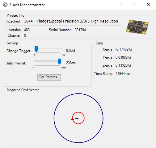
General information about the selected object will be displayed at the top of the window. You can also experiment with the following functionality:
- Modify the change trigger and/or data interval value by dragging the sliders. For more information on these settings, see the data interval/change trigger page.
- Use the Set Params... button to set the calibration parameters. For more information about calibration, see the technical section.
- The measured values reported in Gauss can be seen via labels as well as a graphical diagram. The diagram can help you visualize the magnetic field vector.
- An extremely accurate timestamp is also reported with the Gauss values.
Spatial
Double-click on the Spatial object in order to run the example:
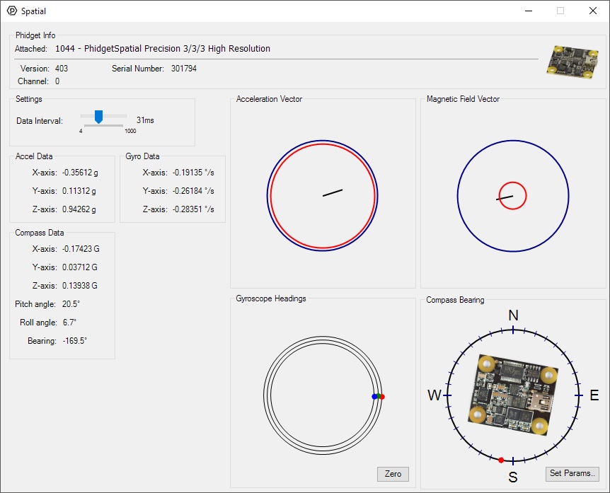
The Spatial example demonstrates that you can receive data from the accelerometer, gyroscope, and magnetometer all at once by using the Spatial object rather than the other three objects individually.
Technical Details
High Resolution Mode
When the 1044 measures an acceleration value with magnitude less than 2g, it will acquire its data from a higher precision accelerometer chip. For these measurements, the average white noise on each axis will be reduced by approximately a factor of ten, and the resolution will increase from 976 μg to 76 μg. Likewise, when the gyroscope measures a rotation value with magnitude less than 300 °/s on the Z-axis or 400 °/s on the X or Y-axis, the noise per axis will be approximately six times lower, and the resolution will increase from 0.07 °/s to 0.02 °/s. The transition from normal to high precision or vice-versa is seamless, with no additional code or equations needed.
3-Axis Accelerometer
The 1044 has a 3-Axis accelerometer that can measure ±8 g's (±78 m/s2) per axis. It will measure both dynamic acceleration (change in velocity) and static acceleration (gravity vector).
For more information on how to use the accelerometer, check the Accelerometer Primer.
3-Axis Gyroscope
For more information on the gyroscope, see the Gyroscope Primer.
3-Axis Magnetometer (Compass)
The magnetometer reports the sum of all magnetic fields acting on the 1044. The earth's magnetic field is only one source that affects this measurement. In order to get accurate bearing data from the magnetometer - (i.e. to find magnetic north as a compass) any interfering magnetic effects need to be calibrated out. For more information about calibration, see the section below, or the Compass Primer.
Any magnetic field that is stationary with respect to the 1044, and less than ± 3 Gauss, can be calibrated out of the magnetic field measurement. This includes both hard and soft iron effects caused by nearby ferrous and magnetic materials. Interfering magnetic fields that vary in strength and orientation with respect to the 1044 cannot be easily calibrated out.
Magnetic field data will become unavailable during every other sample as the compass performs internal calibrations. When this happens, the magneticField array in the SpatialData structure will either have a length of zero, or each element will equal PUNK_DBL, depending on the API being used. This needs to be handled explicitly in the event handling code to avoid erroneous program behavior. The maximum sampling rate of the compass is 125 Hz.
For more information on magnetometers (compasses), see the Compass Primer.
What to do Next
- Programming Languages - Find your preferred programming language here and learn how to write your own code with Phidgets!
- Phidget Programming Basics - Once you have set up Phidgets to work with your programming environment, we recommend you read our page on to learn the fundamentals of programming with Phidgets.