1024 User Guide
Getting Started
Welcome to the 1024 user guide! In order to get started, make sure you have the following hardware on hand:
- 1024 RFID Read/Write Phidget
- USB cable and computer
- compatible RFID tags
Next, you will need to connect the pieces:
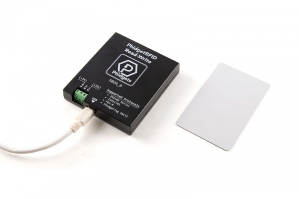
- Connect your device to your computer using the USB cable
Now that you have everything together, let's start using the 1024!
Using the 1024
Phidget Control Panel
In order to demonstrate the functionality of the 1024, the Phidget Control Panel running on a Windows machine will be used.
The Phidget Control Panel is available for use on both macOS and Windows machines.
Windows
To open the Phidget Control Panel on Windows, find the ![]() icon in the taskbar. If it is not there, open up the start menu and search for Phidget Control Panel
icon in the taskbar. If it is not there, open up the start menu and search for Phidget Control Panel
macOS
To open the Phidget Control Panel on macOS, open Finder and navigate to the Phidget Control Panel in the Applications list. Double click on the ![]() icon to bring up the Phidget Control Panel.
icon to bring up the Phidget Control Panel.
For more information, take a look at the getting started guide for your operating system:
Linux users can follow the getting started with Linux guide and continue reading here for more information about the 1024.
First Look
After plugging the 1024 into your computer and opening the Phidget Control Panel, you will see something like this:
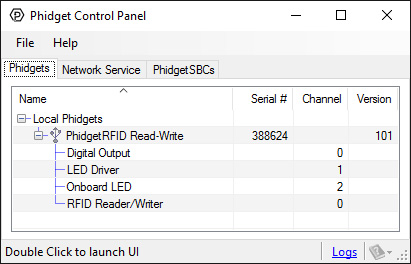
The Phidget Control Panel will list all connected Phidgets and associated objects, as well as the following information:
- Serial number: allows you to differentiate between similar Phidgets.
- Channel: allows you to differentiate between similar objects on a Phidget.
- Version number: corresponds to the firmware version your Phidget is running. If your Phidget is listed in red, your firmware is out of date. Update the firmware by double-clicking the entry.
The Phidget Control Panel can also be used to test your device. Double-clicking on an object will open an example.
RFID (Read/Write)
Double-click on the RFID object labelled RFID Reader/Writer in order to run the example:
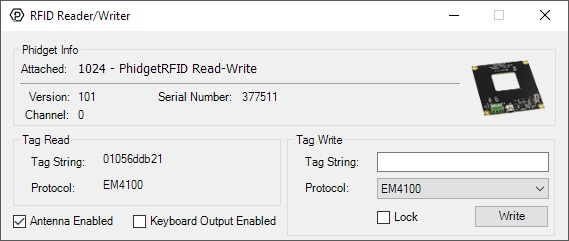
General information about the selected object will be displayed at the top of the window. You can also experiment with the following functionality:
- Bring a compatible tag close to the 1024 and the tag's string and protocol will be displayed. Blank tags will not display anything until they are written to.
- Toggle power to the antenna using the checkbox labelled Antenna Enabled. Toggling antenna power decreases power consumption, however, the 1024 will no longer be able to read or write tags.
- Enabling the Keyboard Output Enabled checkbox will cause your computer to write a string of text whenever a tag is discovered. Park your cursor in an empty text file and try it out!
- Write to a tag by selecting the protocol from the drop-down menu, entering the desired tag in the Tag String text box, and pressing the Write button. If you enable the Lock checkbox, the tag will be permanently written to, and it will be impossible to overwrite.
Digital Output
Double-click on one of the Digital Output objects available in order to run the example. They are labelled Digital Output, LED Driver, and Onboard LED.
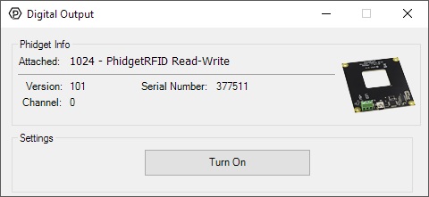
General information about the selected object will be displayed at the top of the window. You can also experiment with the following functionality:
- Toggle the state of the digital output by pressing the button.
Technical Details
Tag Types
We support read-only tags that have been programmed with a supported protocol, as well as T5577 type tags for writing.
T5577
T5577 tags can be written with any of the supported protocols. Fresh T5577 tags that have never been programmed may show up as an EM4100 tag, or may not show up at all. After writing, they will always show up as the written tag. We also support a lock function which prevents a tag from ever being re-written.
Protocols
A protocol is a way of encoding data on an RFID tag. This is not the same as the tag type. For example, we support the T5577 tag type, which can be programmed with any of the protocols which we support. We also support read-only tags which have been programmed in any of these protocols.
We support three reading and writing protocols with the 1024:
EM4100
EM4100 (also known as EM4102) is the protocol that all previous PhidgetRFID readers have supported. Therefore, if you want to use the 1024 to write to writable tags to be read with previous versions of the PhidgetRFID, you need to write them in this protocol first. This protocol encodes 40 bits of arbitrary data. Read-only tags that are factory programmed with this protocol are supposed to be unique.
Phidgets represents this protocol as a 10-digit hex string, include leading 0's (e.g. 0087f3bc91). This is the format to use for writing new tags, and to expect from the tag events.
ISO11785 FDX-B
ISO11785 defines tags used for animal IDs. If you have a pet cat or dog, chances are high that they have one of these tags implanted. FDX-B refers to the way that the ISO11785 data is encoded on the RFID tag, and is the industry-standard encoding scheme.
This tag consists of a 10-bit country code and a 38-bit unique ID.
The country code is ISO 3166. The '999' code is set aside for testing.
The unique ID is 38-bit unsigned, so that's a range of 0 - 274,877,906,943.
Phidgets represents this protocol as a 15-digit decimal number string - concatenated 3-digit country code and 12-digit id. For example, 999000000000123 would represent the testing country code and an id of 123. Please note that the 12-digit id part cannot exceed the 38-bit maximum integer value of 274,877,906,943.
Note that Animal tags with a valid country code are supposed to be unique. Of course, with the 1024 you can freely copy an existing Animal Tag.
PhidgetsTAG
The PhidgetsTAG protocol is an internal protocol only supported by the PhidgetRFID 1024.
This protocol allows storing an ASCII string, up to 24 characters (e.g. I am a Phidgets Tag!)
The ASCII data must be 7-bit, so no extended ASCII support, but standard text is all supported (as well as control codes).
Controlled Outputs
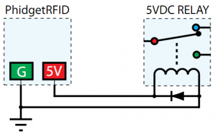
The PhidgetRFID has four outputs - two of which are available to the user, and two of which are for internal control of the Phidget board only. Output 0 is a +5V source from the USB bus through a P-Channel MOSFET with less than one ohm impedance. This can be used to switch a TTL or CMOS device, or it can be used to drive a 5VDC relay such as the Aromat JS1-5V. Output 1 is an LED drive output at 5VDC with maximum 15mA of available current (250 ohm CMOS output). Both Output 0 and 1 are available in hardware at the terminal blocks on the PhidgetRFID board. If Output 0 is used to drive a relay, a fast clamping diode must be placed across the relay drive pins as shown in the diagram on the right. Not doing so can result in permanent damage to the PhidgetRFID board.
| Output | Function | Connection |
| 0 | +5VDC Source | Terminal Block |
| 1 | External LED Drive | Terminal Block |
| LED | Internal LED Drive | Internal Only |
| RF Enable | RF Antenna Enable | Internal Only |
Interfering Signals
If you are using multiple RFID readers, placing them too close together will cause interference when reading tags. You could work around this problem by rapidly "polling" each 1024 by turning the antenna on, checking for tags, and then turning it off in sequence. Of course, this will lengthen the amount of time it takes for your system to read a tag, since you may have to wait for the nearest reader to become active.
Object Speed
When trying to read tags, you should allow the tag to remain within detection range for at least 50ms. Tags moving through the detection area faster than this may not register at all.
Further Reading
For more information on RFID readers and tags, visit the RFID Primer.
What to do Next
- Programming Languages - Find your preferred programming language here and learn how to write your own code with Phidgets!
- Phidget Programming Basics - Once you have set up Phidgets to work with your programming environment, we recommend you read our page on to learn the fundamentals of programming with Phidgets.
Compliance
| Phidgets Inc | |
| 1024_0 | |
| FCC ID: SUT1024-0 |
- This device complies with Part 15 of the FCC Rules. Operation is subject to the following two conditions:
- (1) This device may not cause harmful interference, and
- (2) This device must accept any interference received, including interference that may cause undesired operation.
- Note: The manufacturer is not responsible for any radio or TV interference caused by unauthorized modifications to this equipment. Such modifications could void the user’s authority to operate the equipment.
- The user is cautioned that any changes or modifications not expressly approved by the party responsible for compliance could void the user’s authority to operate the equipment.
- This equipment has been tested and found to comply with the limits for a Class B digital device, pursuant to part 15 of the FCC Rules. These limits are designed to provide reasonable protection against harmful interference in a residential installation. This equipment generates, uses and can radiate radio frequency energy and, if not installed and used in accordance with the instructions, may cause harmful interference to radio communications. However, there is no guarantee that interference will not occur in a particular installation. If this equipment does cause harmful interference to radio or television reception, which can be determined by turning the equipment off and on, the user is encouraged to try to correct the interference by one or more of the following measures:
- • Reorient or relocate the receiving antenna.
- • Increase the separation between the equipment and receiver.
- • Connect the equipment into an outlet on a circuit different from that to which the receiver is connected.
- • Consult the dealer or an experienced radio/TV technician for help.
- This unit was tested with shielded cables on the peripheral devices. Shielded cables must be used with the unit to ensure compliance.