1023 User Guide: Difference between revisions
No edit summary |
No edit summary |
||
| Line 1: | Line 1: | ||
__NOINDEX__ | |||
<metadesc>You can read EM4100 series RFID tags at a distance of up to 6cm with the PhidgetRFID board. Connects to your computer via USB.</metadesc> | <metadesc>You can read EM4100 series RFID tags at a distance of up to 6cm with the PhidgetRFID board. Connects to your computer via USB.</metadesc> | ||
[[Category:UserGuide]] | [[Category:UserGuide]] | ||
Revision as of 20:14, 8 May 2018
Getting Started
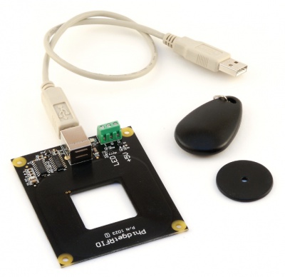
Welcome to the 1023 user guide! In order to get started, make sure you have the following hardware on hand:
- 1023 PhidgetRFID
- USB cable and computer
- compatible RFID tag
Next, you will need to connect the pieces:
- Connect the PhidgetRFID board to the computer using a USB cable.
Now that you have everything together, let's start using the 1023!
Using the 1023
Phidget Control Panel
In order to demonstrate the functionality of the 1023, the Phidget Control Panel running on a Windows machine will be used.
The Phidget Control Panel is available for use on both macOS and Windows machines.
Windows
To open the Phidget Control Panel on Windows, find the ![]() icon in the taskbar. If it is not there, open up the start menu and search for Phidget Control Panel
icon in the taskbar. If it is not there, open up the start menu and search for Phidget Control Panel
macOS
To open the Phidget Control Panel on macOS, open Finder and navigate to the Phidget Control Panel in the Applications list. Double click on the ![]() icon to bring up the Phidget Control Panel.
icon to bring up the Phidget Control Panel.
For more information, take a look at the getting started guide for your operating system:
Linux users can follow the getting started with Linux guide and continue reading here for more information about the 1023.
First Look
After plugging the 1023 into your computer and opening the Phidget Control Panel, you will see something like this:
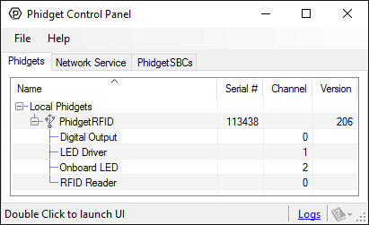
The Phidget Control Panel will list all connected Phidgets and associated objects, as well as the following information:
- Serial number: allows you to differentiate between similar Phidgets.
- Channel: allows you to differentiate between similar objects on a Phidget.
- Version number: corresponds to the firmware version your Phidget is running. If your Phidget is listed in red, your firmware is out of date. Update the firmware by double-clicking the entry.
The Phidget Control Panel can also be used to test your device. Double-clicking on an object will open an example.
RFID
Double-click on the RFID object labelled RFID Reader in order to run the example:
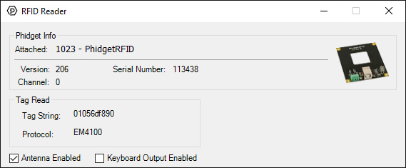
General information about the selected object will be displayed at the top of the window. You can also experiment with the following functionality:
- Bring a compatible tag close to the 1023 and the tag's string and protocol will be displayed.
- Toggle power to the antenna using the checkbox labelled Antenna Enabled. Toggling antenna power decreases power consumption, however, the 1023 will no longer be able to read tags.
- Enabling the Keyboard Output Enabled checkbox will cause your computer to write a string of text whenever a tag is discovered. Park your cursor in an empty text file and try it out!
Digital Output
Double-click on one of the Digital Output objects available in order to run the example. They are labelled Digital Output, LED Driver, and Onboard LED.
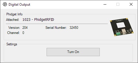
General information about the selected object will be displayed at the top of the window. You can also experiment with the following functionality:
- Toggle the state of the digital output by pressing the button.
Technical Details
Controlled Outputs
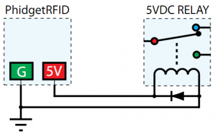
The PhidgetRFID has four outputs - two of which are available to the user. Output 0 is a 5VDC source from the USB bus through a P-Channel MOSFET with less than one ohm impedance. This can be used to switch a TTL or CMOS device, or it can be used to drive a 5VDC relay such as the Aromat JS1-5V. Output 1 is an LED drive output at 5VDC with maximum 15mA of available current (250 ohm CMOS output). Both Output 0 and 1 are available in hardware at the terminal blocks on the PhidgetRFID board. If Output 0 is used to drive a relay, a fast clamping diode must be placed across the relay drive pins as shown in the diagram on the right. Not doing so can result in permanent damage to the PhidgetRFID board.
| Output | Function | Connection |
| 0 | +5VDC Source | Terminal Block |
| 1 | External LED Drive | Terminal Block |
| LED | Internal LED Drive | Internal Only |
| RF Enable | RF Antenna Enable | Internal Only |
Interfering Signals
If you are using multiple RFID readers, placing them too close together will cause interference when reading tags. You can work around this problem by rapidly "polling" each 1023 by turning the antenna on, checking for tags, and then turning it off in sequence. Of course, this will lengthen the amount of time it takes for your system to read a tag, since you may have to wait for the nearest reader to become active.
Object Speed
When trying to read tags, you should allow the tag to remain within detection range for at least 50ms. Tags moving through the detection area faster than this may not register.
Further Reading
For more information on RFID readers and tags, visit the RFID Primer.
What to do Next
- Programming Languages - Find your preferred programming language here and learn how to write your own code with Phidgets!
- Phidget Programming Basics - Once you have set up Phidgets to work with your programming environment, we recommend you read our page on to learn the fundamentals of programming with Phidgets.