1023 User Guide: Difference between revisions
| Line 88: | Line 88: | ||
<br clear=all> | <br clear=all> | ||
===Interfering Signals=== | |||
If you are using multiple RFID readers, don't put them too close together or you will get interference when reading tags. | |||
===Further Reading=== | |||
For more information on RFID readers and tags, visit the [[RFID Primer]]. | For more information on RFID readers and tags, visit the [[RFID Primer]]. | ||
Revision as of 18:27, 8 August 2012
Getting Started
Checking the Contents
|
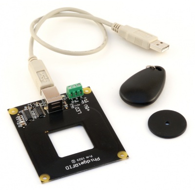
You should have received:
|
In order to test your new Phidget you will also need:
| |
Connecting the Pieces
|
Connect the PhidgetRFID board to the computer using the USB cable. |
| |
Testing Using Windows 2000 / XP / Vista / 7
Make sure you have the current version of the Phidget library installed on your PC. If you don't, follow these steps:
- Go to the Quick Downloads section on the Windows page
- Download and run the Phidget21 Installer (32-bit, or 64-bit, depending on your system)
- You should see the
 icon on the right hand corner of the Task Bar.
Running Phidgets Sample Program
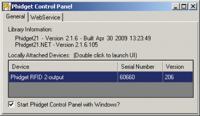
Double clicking on the ![]() icon loads the Phidget Control Panel; we will use this program to ensure that your new Phidget works properly.
icon loads the Phidget Control Panel; we will use this program to ensure that your new Phidget works properly.
The source code for the PhidgetRFID-Full sample program can be found in the quick downloads section on the C# Language Page. If you'd like to see examples in other languages, you can visit our Languages page.
Updating Device Firmware
If an entry in this list is red, it means the firmware for that device is out of date. Double click on the entry to be given the option of updating the firmware. If you choose not to update the firmware, you can still run the example for that device after refusing.
|
Double Click on the |
| |
|
|
Testing Using Mac OS X
- Go to the Quick Downloads section on the Mac OS X page
- Download and run the Phidget OS X Installer
- Click on System Preferences >> Phidgets (under Other) to activate the Preference Pane
- Make sure that the Phidget RFID is properly attached.
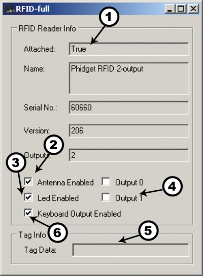
- Double Click on Phidget RFID in the Phidget Preference Pane to bring up the RFID-full Sample program. This program will function in a similar way as the Windows version.
Using Linux
For a step-by-step guide on getting Phidgets running on Linux, check the Linux page.
Using Windows Mobile / CE 5.0 / CE 6.0
Technical Details
Controlled Outputs
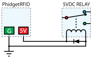
The PhidgetRFID has four outputs - two of which are available to the user, and two of which are for internal control of the Phidget board only. Output 0 is a +5V source from the USB bus through a P-Channel MOSFET with less than one ohm impedance. This can be used to switch a TTL or CMOS device, or it can be used to drive a 5VDC relay such as the Aromat JS1-5V. Output 1 is an LED drive output at 5VDC with maximum 15mA of available current (250 ohm CMOS output). Both Output 0 and 1 are available in hardware at the terminal blocks on the PhidgetRFID board. If Output 0 is used to drive a relay, a fast clamping diode must be placed across the relay drive pins as shown in the diagram on the right. Not doing so can result in permanent damage to the PhidgetRFID board.
| Output | Function | Connection |
|---|---|---|
| 3019_0 | Molex 50-57-940 | 50 |
| 0 | +5VDC Source | Terminal Block |
| 1 | External LED Drive | Terminal Block |
| LED | Internal LED Drive | Internal Only |
| RF Enable | RF Antenna Enable | Internal Only |
Interfering Signals
If you are using multiple RFID readers, don't put them too close together or you will get interference when reading tags.
Further Reading
For more information on RFID readers and tags, visit the RFID Primer.
API
Functions
Events
Product History
Template:UGhist Template:UGrow Template:UGrow Template:UGrow Template:UGrow Template:UGrow Template:UGrow Template:UGrow