1015 User Guide
Getting Started
Welcome to the 1015 user guide! In order to get started, make sure you have the following hardware on hand:
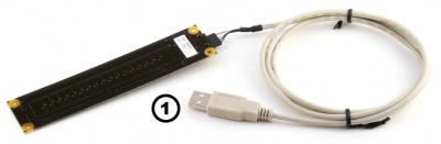
- 1015 PhidgetLinearTouch and custom USB cable
- computer
Next, you will need to connect the pieces:
- Connect the Phidget to your computer using the USB cable
Now that you have everything together, let's start using the 1015!
Testing Using Windows
Phidget Control Panel
In order to demonstrate the functionality of the 1015, the Phidget Control Panel running on a Windows machine will be used.
The Phidget Control Panel is available for use on both macOS and Windows machines.
Windows
To open the Phidget Control Panel on Windows, find the ![]() icon in the taskbar. If it is not there, open up the start menu and search for Phidget Control Panel
icon in the taskbar. If it is not there, open up the start menu and search for Phidget Control Panel
macOS
To open the Phidget Control Panel on macOS, open Finder and navigate to the Phidget Control Panel in the Applications list. Double click on the ![]() icon to bring up the Phidget Control Panel.
icon to bring up the Phidget Control Panel.
For more information, take a look at the getting started guide for your operating system:
Linux users can follow the getting started with Linux guide and continue reading here for more information about the 1015.
First Look
After plugging the 1015 into your computer and opening the Phidget Control Panel, you will see something like this:
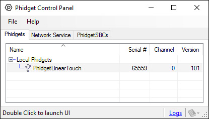
The Phidget Control Panel will list all connected Phidgets and associated objects, as well as the following information:
- Serial number: allows you to differentiate between similar Phidgets.
- Channel: allows you to differentiate between similar objects on a Phidget.
- Version number: corresponds to the firmware version your Phidget is running. If your Phidget is listed in red, your firmware is out of date. Update the firmware by double-clicking the entry.
The Phidget Control Panel can also be used to test your device. Double-clicking on an object will open an example.
Capacitive Touch
Double-click on the Capacitive Touch object labelled PhidgetLinearTouch in order to run the example:
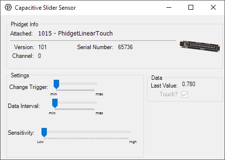
General information about the selected object will be displayed at the top of the window. You can also experiment with the following functionality:
- Modify the change trigger and/or data interval value by dragging the sliders. For more information on these settings, see the data interval/change trigger page.
- The sensitivity of the 1015 can also be adjusted. The higher the sensitivity, the more susceptible the 1015 will be to sensing touch.
- When the 1015 senses a touch, the state of the Touch? checkbox will change.
- The Last Value label corresponds to the location of the last touch along the 1015.
Technical Details
The 1015 is actually a capacitive-charge sensor, detecting changes in the capacitance between the on-board electrodes and the object making contact. The side of the circuit board opposite the connector and components is the side intended for contact. The internal sensor used for charge-detection is a Quantum Research Group QT401 Sensor.
Device Inputs
The 1015 appears to the Phidget software libraries as a CapacitiveTouch object. Sliding a finger along the touch sensor varies the axis value from 0 to 1 in approximately 125 discrete steps. When the finger is removed, the final measured value is retained.
For many projects it is required that the highest and lowest available values be more readily accessible than the full range. The PhidgetLinearTouch board has been designed so that the end-zones of the touch area have a greater contact area, allowing for effective maximum/minimum value control. If it is desired to use the touch slider as an array of buttons, or a combination of an array of buttons and a smaller slide-touch area, one must only interpret specific sub-ranges of sensor values differently in software depending upon the intended use. If sub-ranges of values are to be used as buttons, it is recommended that a small range of sensor values be left between the subranges where a null-response is observed.
Dielectric Separation
The 1015 has been left without components on the contact side so that it may be mounted behind a sheet of glass or plastic. The recommended thickness of separation material is 1/8". Silicon adhesive is recommended when attaching the Phidget to the material; standing the PhidgetLinearTouch off or creating space between the separation material and the Phidget can cause false-triggering to occur. It should be noted that materials thicker than 1/8" may work, but will require a larger surface area of contact to ensure proper triggering (i.e. two fingers instead of one).
What to do Next
- Programming Languages - Find your preferred programming language here and learn how to write your own code with Phidgets!
- Phidget Programming Basics - Once you have set up Phidgets to work with your programming environment, we recommend you read our page on to learn the fundamentals of programming with Phidgets.