1014 User Guide: Difference between revisions
No edit summary |
No edit summary |
||
| Line 2: | Line 2: | ||
===Required Hardware=== | ===Required Hardware=== | ||
* A 1014 Phidget InterfaceKit[{{SERVER}}/products.php?product_id=1014 1014 Phidget InterfaceKit] | * A 1014 Phidget InterfaceKit [{{SERVER}}/products.php?product_id=1014 1014 Phidget InterfaceKit] | ||
* A power supply and load to test the relay | * A power supply and load to test the relay | ||
* A USB cable | * A USB cable | ||
Revision as of 21:20, 5 June 2017
Required Hardware
- A 1014 Phidget InterfaceKit 1014 Phidget InterfaceKit
- A power supply and load to test the relay
- A USB cable
- A computer
Connecting the Pieces
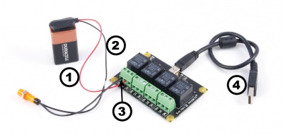
- Connect the load and power supply in series.
- Connect one end to the 0C (Common) terminal, and the other to the NO (Normally open) terminal.
- Connect the 1014 to your computer using the USB cable.
Testing Using Windows
Phidget Control Panel
In order to demonstrate the functionality of the 1014, the Phidget Control Panel running on a Windows machine will be used.
The Phidget Control Panel is available for use on both macOS and Windows machines.
Windows
To open the Phidget Control Panel on Windows, find the ![]() icon in the taskbar. If it is not there, open up the start menu and search for Phidget Control Panel
icon in the taskbar. If it is not there, open up the start menu and search for Phidget Control Panel
macOS
To open the Phidget Control Panel on macOS, open Finder and navigate to the Phidget Control Panel in the Applications list. Double click on the ![]() icon to bring up the Phidget Control Panel.
icon to bring up the Phidget Control Panel.
For more information, take a look at the getting started guide for your operating system:
Linux users can follow the getting started with Linux guide and continue reading here for more information about the 1014.
First Look
After plugging the 1014 into your computer and opening the Phidget Control Panel, you will see something like this:
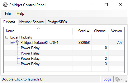
The Phidget Control Panel will list all connected Phidgets and associated objects, as well as the following information:
- Serial number: allows you to differentiate between similar Phidgets.
- Channel: allows you to differentiate between similar objects on a Phidget.
- Version number: corresponds to the firmware version your Phidget is running. If your Phidget is listed in red, your firmware is out of date. Update the firmware by double-clicking the entry.
The Phidget Control Panel can also be used to test your device. Double-clicking on an object will open an example.
Digital Output
Double-click on a Digital Output object {{{2}}} in order to run the example: [[Image:{{{1}}}_DigitalOutput_Example.jpg|center|link=]]
General information about the selected object will be displayed at the top of the window. You can also experiment with the following functionality:
- Toggle the state of the digital output by pressing the button.
Testing Using Mac OS X
- Go to the Quick Downloads section on the Mac OS X page.
- Download and run the Phidget OS X Installer
- Click on System Preferences >> Phidgets (under Other) to activate the Preference Pane
- Make sure your device is properly attached
- Double click on your device's objects in the listing to open them. The Preference Pane and examples will function very similarly to the ones described above in the Windows section.
Testing Using Linux
For a general step-by-step guide on getting Phidgets running on Linux, see the Linux page.
Using a Remote OS
We recommend testing your Phidget on a desktop OS before moving on to remote OS. Once you've tested your Phidget, you can go to the PhidgetSBC, or iOS pages to learn how to proceed.
Technical Details
Relays
A relay is an electrically-controlled switch. Although many types of electrical switches exist, a relay’s mechanical nature gives it the advantage of reliability and current-switching capacity. The main disadvantage to using mechanical relays is their limited life-span, as opposed to solid state relays who do not suffer from this drawback. For more information, check the Mechanical Relay Primer and the Solid State Relay Primer.
Using a Digital Output Relay
Relays have a connection scheme determined by the arrangement of contacts within the relay. Because relays are a type of switch, they are defined in the same way other electromechanical switches are defined.
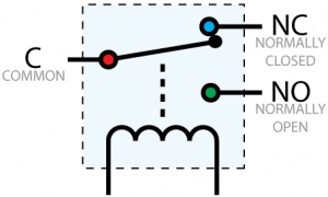
In switch schemes, the number of poles represents the number of common terminals a switch has, and the number of throws represents the number of switchable terminals that exist for each pole. The relays used in the InterfaceKit 0/0/4 are SPDT relays: single pole, double throw. The internal construction of this type of relay is depicted in the diagram above. Many other types of relays exist: SPST, DPDT, and DPST, to name a few.
In an SPDT relay, one of the throw terminals is labelled Normally Closed (NC), and the other is labelled Normally Open (NO). As the name indicates, the normally closed terminal is the terminal connected to common when the relay coil is not powered. When the relay coil is energized by the relay control circuit, the electromagnetic field of the coil forces the switch element inside the relay to break its contact with the normally closed terminal and make contact with the normally open terminal. The switch element would then connect the normally open terminal and the common terminal.
Using Relays as an H-Bridge for Motor Forward/Reverse
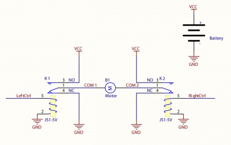
Connect the load (typically a DC Motor) to the COM terminals of the relay. The NormallyOpen (NO) terminals are connected to the power supply (VCC), and the Normally-Closed (NC) terminals are connected to the ground (GND) of the power supply. You can toggle the corresponding output to switch the relays.
Looking at the diagram, when LeftCtrl is enabled and RightCtrl is disabled, the current will flow from the NO terminal of relay K1 through the motor and into the NC terminal of relay K2. This will cause the motor to rotate in one direction.
Similarily, if LeftCtrl is disabled and RightCtrl is enabled, the current will flow from the NO terminal of relay K2 through the motor and into the NC terminal of relay K1. This will cause the motor to rotate in the opposite direction.
When both LeftCtrl and RightCtrl are disabled, both ends of the motor will be shorted to ground and no current will flow. When both leftCtrl and RightCtrl are enabled, both ends of the motor will be shorted to VCC and again, no current will flow.
Wetting Current
When a relay is in one switch position for a period of time, oxidation of the open contact(s) can occur. Depending upon the internal coating material of the contacts, oxide films of varying density will be displaced upon the surface of open contacts; this film acts as an insulator to current flow. When the relay is switched, a certain amount of current flowing through the contacts, known as the wetting current, is required to remove the film of oxides and ensure proper conduction. Because of this requirement, these relays are not reliable for signal switching. Check the specification table for your relay board to find out the Minimum Load Current ("Wetting Current").
Load Noise
If highly inductive loads are used with the InterfaceKit, it is recommended that a noise limiting component be used to prevent damage to the device. An MOV, TVS diode, or kickback diode (for DC applications) shunted across the load will assist in dissipating voltage transients.
What to do Next
- Programming Languages - Find your preferred programming language here and learn how to write your own code with Phidgets!
- Phidget Programming Basics - Once you have set up Phidgets to work with your programming environment, we recommend you read our page on to learn the fundamentals of programming with Phidgets.