1012 User Guide: Difference between revisions
No edit summary |
No edit summary |
||
| Line 1: | Line 1: | ||
[[Category:UserGuide]] | [[Category:UserGuide]] | ||
===Required Hardware=== | ===Required Hardware=== | ||
| Line 10: | Line 8: | ||
===Connecting the Pieces=== | ===Connecting the Pieces=== | ||
[[Image:1012_0_Connecting_the_Hardware.jpg|300px|right|link=]] | |||
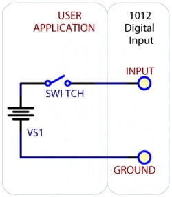
# Digital Inputs: By connecting a power supply and a switch (or the 5V pin of the 1012 and a switch) you can test the digital inputs of the 1012. | # Digital Inputs: By connecting a power supply and a switch (or the 5V pin of the 1012 and a switch) you can test the digital inputs of the 1012. | ||
# Open Collector Digital Outputs: Connect a load (like a light bulb or LED) in series with a power supply and connect one end of the series to a digital output and the other to ground, as pictured. | # Open Collector Digital Outputs: Connect a load (like a light bulb or LED) in series with a power supply and connect one end of the series to a digital output and the other to ground, as pictured. | ||
Revision as of 20:58, 26 August 2016
Required Hardware
- A 1012 Phidget InterfaceKit
- Switches and batteries, or other devices to test the digial I/O of the 1012
- A USB Cable
- A computer
Connecting the Pieces
- Digital Inputs: By connecting a power supply and a switch (or the 5V pin of the 1012 and a switch) you can test the digital inputs of the 1012.
- Open Collector Digital Outputs: Connect a load (like a light bulb or LED) in series with a power supply and connect one end of the series to a digital output and the other to ground, as pictured.
- Connect the Phidget to your computer using the USB cable
Testing Using Windows
Phidget Control Panel
In order to demonstrate the functionality of the 1012, the Phidget Control Panel running on a Windows machine will be used.
The Phidget Control Panel is available for use on both macOS and Windows machines.
Windows
To open the Phidget Control Panel on Windows, find the ![]() icon in the taskbar. If it is not there, open up the start menu and search for Phidget Control Panel
icon in the taskbar. If it is not there, open up the start menu and search for Phidget Control Panel
macOS
To open the Phidget Control Panel on macOS, open Finder and navigate to the Phidget Control Panel in the Applications list. Double click on the ![]() icon to bring up the Phidget Control Panel.
icon to bring up the Phidget Control Panel.
For more information, take a look at the getting started guide for your operating system:
Linux users can follow the getting started with Linux guide and continue reading here for more information about the 1012.
First Look
After plugging the 1012 into your computer and opening the Phidget Control Panel, you will see something like this:
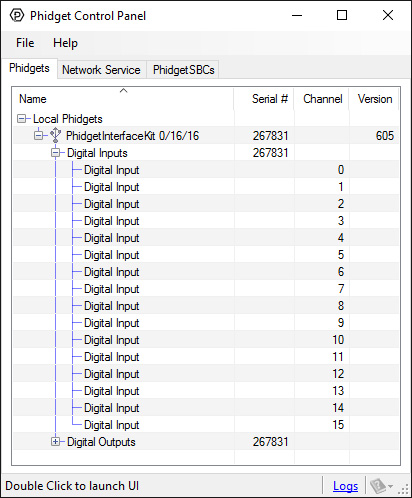
The Phidget Control Panel will list all connected Phidgets and associated objects, as well as the following information:
- Serial number: allows you to differentiate between similar Phidgets.
- Channel: allows you to differentiate between similar objects on a Phidget.
- Version number: corresponds to the firmware version your Phidget is running. If your Phidget is listed in red, your firmware is out of date. Update the firmware by double-clicking the entry.
The Phidget Control Panel can also be used to test your device. Double-clicking on an object will open an example.
Digital Input
Double-click on a Digital Input object in order to run the example: [[Image:{{{1}}}_DigitalInputAL_Example.jpg|center|link=]]
General information about the selected object will be displayed at the top of the window. You can also experiment with the following functionality:
- This is an active-high device, therefore, it will be true when connected to a high input and false when connected to ground.
Testing Using Mac OS X
- Go to the Quick Downloads section on the Mac OS X page.
- Download and run the Phidget OS X Installer
- Click on System Preferences >> Phidgets (under Other) to activate the Preference Pane
- Make sure your device is properly attached
- Double click on your device's objects in the listing to open them. The Preference Pane and examples will function very similarly to the ones described above in the Windows section.
Testing Using Linux
For a general step-by-step guide on getting Phidgets running on Linux, see the Linux page.
Using a Remote OS
We recommend testing your Phidget on a desktop OS before moving on to remote OS. Once you've tested your Phidget, you can go to the PhidgetSBC, or iOS pages to learn how to proceed.
Technical Details
Digital Inputs
There is built-in filtering on the digital input, to eliminate false triggering from electrical noise. The digital input is first RC filtered by a 10K/100nF node, which will reject noise of higher frequency than 1Khz. This filter generally eliminates the need to shield the digital input from inductive and capacitive coupling likely to occur in wiring harnesses.
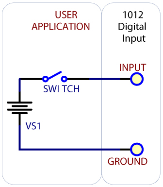
Monitoring a Switch
Full-Sized Image
To test your digital input, wire it up to a switch as shown in the diagram. The power supply VS1 needs to be within 4-30V DC in order to guarantee a response from the digital input when the switch is closed.
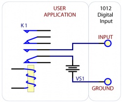
Monitoring the Position of a Relay
If you have a double-pole relay (that is, a relay that is designed to close two switches at once with the same control input), you can switch a load with one pole, and monitor the state of the relay with the other pole. This can come in handy as a safety feature- if the relay were to fail, your software would normally not have any way of knowing.
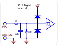
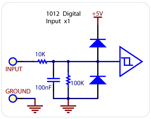
Functional Block Diagram
Unlike typical Phidgets Digital Inputs, these are capable of receiving up to 30VDC. These inputs are active high: A voltage of 4VDC to 30VDC will be read as True or logical 1; below 1VDC will be read as a False or logical 0. The input is high impedance, which means current flowing into the Phidget device will be limited. Ground terminals are provided in multiple locations along the input terminal strip; it is recommended that the ground terminal located nearest the input terminal be used.
Open Collector Digital Outputs
For more information, check the Open Collector Digital Output Primer.
What to do Next
- Programming Languages - Find your preferred programming language here and learn how to write your own code with Phidgets!
- Phidget Programming Basics - Once you have set up Phidgets to work with your programming environment, we recommend you read our page on to learn the fundamentals of programming with Phidgets.
Product History
Template:UGhist Template:UGrow2 Template:UGrow2 Template:UGrow2 Template:UGrow2 Template:UGrow2 Template:UGrow2 Template:UGrow2 Template:UGrow2