1011 User Guide: Difference between revisions
No edit summary |
|||
| (21 intermediate revisions by 5 users not shown) | |||
| Line 1: | Line 1: | ||
__NOINDEX__ | |||
<metadesc>This Phidget InterfaceKit USB Dongle has 2 Analog Inputs, 2 Digital Inputs and 2 Digital Outputs. Ideal when when space is limited.</metadesc> | |||
[[Category:UserGuide]] | [[Category:UserGuide]] | ||
==Getting Started== | ==Getting Started== | ||
{{UGIntro|1011}} | |||
*[{{SERVER}}/products.php?product_id=1011 1011 Phidget InterfaceKit] and [{{SERVER}}/products.php?product_id=3013 12-Wire Custom Cable] | |||
*computer | |||
*something to use with the 1011 (e.g. LEDs, switches, analog sensor, etc.) | |||
{{ | Next, you will need to connect the pieces: | ||
[[Image:1011_0_Connecting_The_Hardware.jpg|500px|right|link=]] | |||
#Connect the 12-Wire Custom Cable to the 1011 | |||
#Connect any/all test hardware to the 1011. View the [[#Technical_Details|technical section]] for help. | |||
#Connect the 1010 to the computer. | |||
<br clear="all"> | |||
{{UGIntroDone|1011}} | |||
==Using the 1011== | |||
{{UGcontrolpanel|1011}} | |||
{{ | {{ugVoltageInputSensor|1011}} | ||
{{ | {{ugVoltageRatioSensor|1011}} | ||
}} | |||
{{ugDigitalInput|1011|{{UGDigitalInputActiveLow}}}} | |||
{{ | {{ugDigitalOutput|1011|}} | ||
{{ugAddressingInformation}} | |||
{{ | {{ugUsingYourOwnProgram|1011}} | ||
==Technical Details== | ==Technical Details== | ||
[[File:1011_0_Connector_Diagram.jpg|500px|link=|center]] | |||
===Replacing the I/O Interface Cable=== | ===Replacing the I/O Interface Cable=== | ||
If your I/O interface cable gets damaged, you can remove it and replace it with 3013 | If your I/O interface cable gets damaged, you can remove it and replace it with [{{SERVER}}/products.php?product_id=3013 PhidgetInterfaceKit 2/2/2 replacement cable]. Pull hard on the connector until it comes out. | ||
*Note: the cable is designed to be permanently attached to the 1011. We strongly recommend that you limit the number of times you remove the assembly from the 1011. | |||
These connectors are also commonly available. Their part numbers are listed below: | |||
{| class="wikitable" | |||
These connectors are commonly available | |align="center" style="background:#f0f0f0;"|'''Manufacturer''' | ||
|align="center" style="background:#f0f0f0;"|'''Part Number''' | |||
|align="center" style="background:#f0f0f0;"|'''Description''' | |||
| | |||
| | |||
|- | |- | ||
| | |align=center| Hirose Electric | ||
| | |align=center| DF11-12DP-2DS(24) | ||
| | |align=left | 2mm Double-Row Connector (Right Angle Pin Header) | ||
|- | |- | ||
| | |align=center| Hirose Electric | ||
| | |align=center| DF11-12DS-2C | ||
| | |align=left | 2mm Double-Row Connector (Crimping Socket) | ||
|} | |} | ||
For part numbers on the analog sensor cables, see the mechanical section of the [[Analog Input Primer#Mechanical Specifications|Analog Input Primer]]. | |||
===Further Reading=== | ===Further Reading=== | ||
If you want to know more about the input/output capabilities of the 1011 InterfaceKit, check the [[Digital Input Primer]], [[Digital | If you want to know more about the input/output capabilities of the 1011 InterfaceKit, check the [[Digital Input Primer]], [[InterfaceKit Digital Outputs]] page, and the [[Analog Input Primer]]. | ||
{{UGnext|}} | |||
{{ | |||
Revision as of 16:02, 17 October 2019
Getting Started
Welcome to the 1011 user guide! In order to get started, make sure you have the following hardware on hand:
- 1011 Phidget InterfaceKit and 12-Wire Custom Cable
- computer
- something to use with the 1011 (e.g. LEDs, switches, analog sensor, etc.)
Next, you will need to connect the pieces:
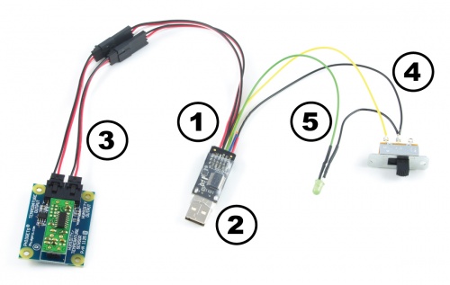
- Connect the 12-Wire Custom Cable to the 1011
- Connect any/all test hardware to the 1011. View the technical section for help.
- Connect the 1010 to the computer.
Now that you have everything together, let's start using the 1011!
Using the 1011
Phidget Control Panel
In order to demonstrate the functionality of the 1011, the Phidget Control Panel running on a Windows machine will be used.
The Phidget Control Panel is available for use on both macOS and Windows machines.
Windows
To open the Phidget Control Panel on Windows, find the ![]() icon in the taskbar. If it is not there, open up the start menu and search for Phidget Control Panel
icon in the taskbar. If it is not there, open up the start menu and search for Phidget Control Panel
macOS
To open the Phidget Control Panel on macOS, open Finder and navigate to the Phidget Control Panel in the Applications list. Double click on the ![]() icon to bring up the Phidget Control Panel.
icon to bring up the Phidget Control Panel.
For more information, take a look at the getting started guide for your operating system:
Linux users can follow the getting started with Linux guide and continue reading here for more information about the 1011.
First Look
After plugging the 1011 into your computer and opening the Phidget Control Panel, you will see something like this:
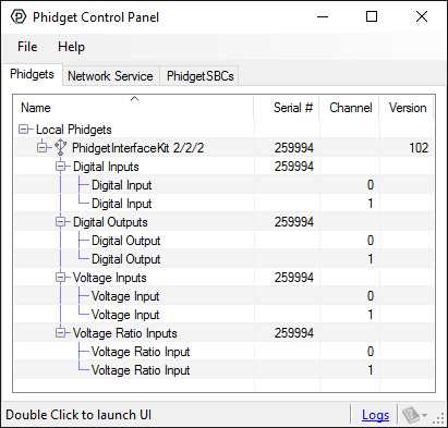
The Phidget Control Panel will list all connected Phidgets and associated objects, as well as the following information:
- Serial number: allows you to differentiate between similar Phidgets.
- Channel: allows you to differentiate between similar objects on a Phidget.
- Version number: corresponds to the firmware version your Phidget is running. If your Phidget is listed in red, your firmware is out of date. Update the firmware by double-clicking the entry.
The Phidget Control Panel can also be used to test your device. Double-clicking on an object will open an example.
Voltage Input
Double-click on a Voltage Input object in order to run the example:
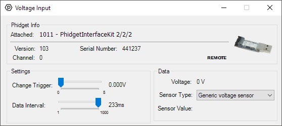
General information about the selected object will be displayed at the top of the window. You can also experiment with the following functionality:
- Modify the change trigger and/or data interval value by dragging the sliders. For more information on these settings, see the data interval/change trigger page.
- If you have an analog sensor connected that you bought from us, you can select it from the Sensor Type drop-down menu. The example will then convert the voltage into a more meaningful value based on your sensor, with units included, and display it beside the Sensor Value label. Converting voltage to a Sensor Value is not specific to this example, it is handled by the Phidget libraries, with functions you have access to when you begin developing!
For more information about Voltage Inputs, check out the Voltage Input Primer.
Voltage Ratio Input
Double-click on a Voltage Ratio Input object in order to run the example:
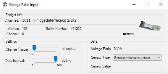
General information about the selected object will be displayed at the top of the window. You can also experiment with the following functionality:
- The voltage ratio is reported in Volts per Volt. For example, if the Phidget is providing 5V and the sensor is sending back 2.5V, the ratio will be 0.5V/V.
- Modify the change trigger and/or data interval value by dragging the sliders. For more information on these settings, see the data interval/change trigger page.
- If you have an analog sensor connected that you bought from us, you can select it from the Sensor Type drop-down menu. The example will then convert the voltage into a more meaningful value based on your sensor, with units included, and display it beside the Sensor Value label. Converting voltage to a Sensor Value is not specific to this example, it is handled by the Phidget libraries, with functions you have access to when you begin developing!
For more information about Voltage Ratio Inputs, check out the Voltage Ratio Input Primer.
Digital Input
Double-click on a Digital Input object in order to run the example:
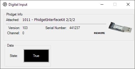
General information about the selected object will be displayed at the top of the window. You can also experiment with the following functionality:
- This is an active-low device, therefore, it will be true when connected to ground, and false when connected to a high voltage.
For more information about Digital Inputs, take a look at the Digital Input Primer
Digital Output
Double-click on a Digital Output object in order to run the example:
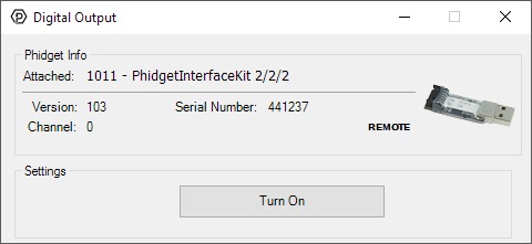
General information about the selected object will be displayed at the top of the window. You can also experiment with the following functionality:
- Toggle the state of the digital output by pressing the button.
Finding The Addressing Information
Before you can access the device in your own code, and from our examples, you'll need to take note of the addressing parameters for your Phidget. These will indicate how the Phidget is physically connected to your application. For simplicity, these parameters can be found by clicking the button at the top of the Control Panel example for that Phidget.

In the Addressing Information window, the section above the line displays information you will need to connect to your Phidget from any application. In particular, note the Channel Class field as this will be the API you will need to use with your Phidget, and the type of example you should use to get started with it. The section below the line provides information about the network the Phidget is connected on if it is attached remotely. Keep track of these parameters moving forward, as you will need them once you start running our examples or your own code.

Using Your Own Program
You are now ready to start writing your own code for the device. The best way to do that is to start from our Code Samples.
Select your programming language of choice from the drop-down list to get an example for your device. You can use the options provided to further customize the example to best suit your needs.
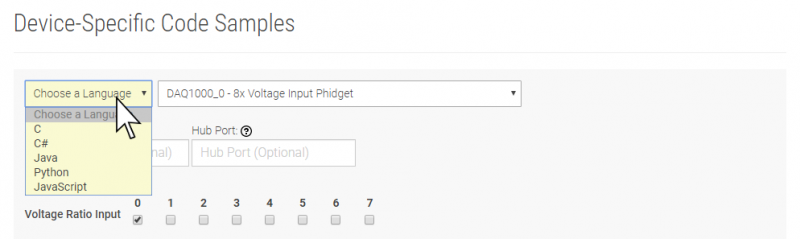
Once you have your example, you will need to follow the instructions on the page for your programming language to get it running. To find these instructions, select your programming language from the Programming Languages page.
Technical Details
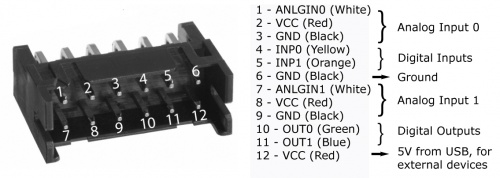
Replacing the I/O Interface Cable
If your I/O interface cable gets damaged, you can remove it and replace it with PhidgetInterfaceKit 2/2/2 replacement cable. Pull hard on the connector until it comes out.
- Note: the cable is designed to be permanently attached to the 1011. We strongly recommend that you limit the number of times you remove the assembly from the 1011.
These connectors are also commonly available. Their part numbers are listed below:
| Manufacturer | Part Number | Description |
| Hirose Electric | DF11-12DP-2DS(24) | 2mm Double-Row Connector (Right Angle Pin Header) |
| Hirose Electric | DF11-12DS-2C | 2mm Double-Row Connector (Crimping Socket) |
For part numbers on the analog sensor cables, see the mechanical section of the Analog Input Primer.
Further Reading
If you want to know more about the input/output capabilities of the 1011 InterfaceKit, check the Digital Input Primer, InterfaceKit Digital Outputs page, and the Analog Input Primer.
What to do Next
- Programming Languages - Find your preferred programming language here and learn how to write your own code with Phidgets!
- Phidget Programming Basics - Once you have set up Phidgets to work with your programming environment, we recommend you read our page on to learn the fundamentals of programming with Phidgets.