1010 User Guide
Getting Started
In order to use the 1010, you must be comfortable with designing your own circuit. You will need to understand the “signals” coming from and going to the 1010.
If you are not familiar with Phidgets, we recommend purchasing a 1018 to familiarize yourself with Phidget concepts before attempting to design the 1010 into your system.
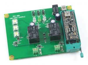
Here is an example of a small board we have built for internal testing purposes. We have some LEDs, 2 relays, a power jack, and a couple of connectors.
Technical Details
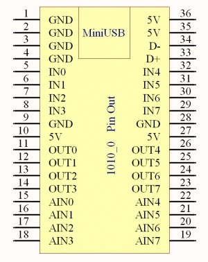
5V is the USB Power Supply - made available to your application if it requires a small amount of current (<400mA). All 5V pins are connected together internally.
GND is the USB Ground - all ground pins are connected together internally.
IN0 - IN7 are digital inputs. For more information, see the Digital Input Primer.
OUT0 - OUT7 are digital outputs. For more information, see the Digital Output Primer.
AIN0 - AIN7 are analog inputs. For more information, see the Analog Input Primer.
For dimensions, please refer to the Mechanical Drawing on the Product Page.