1002 User Guide: Difference between revisions
No edit summary |
No edit summary |
||
| (46 intermediate revisions by 5 users not shown) | |||
| Line 1: | Line 1: | ||
__NOINDEX__ | |||
<metadesc>The Phidget Analog 4-Output produces a voltage from -10V to +10V and connects to your computer via USB.</metadesc> | |||
[[Category:UserGuide]] | [[Category:UserGuide]] | ||
==Getting Started== | ==Getting Started== | ||
{{UGIntro|1002}} | |||
*[{{SERVER}}/products.php?product_id=1002 1002 PhidgetAnalog 4-Output] | |||
*USB cable and computer | |||
*something to use with the 1002 (multimeter, oscilloscope, device with voltage input, etc.) | |||
Next, you will need to connect the pieces: | |||
[[Image:1002_0_Connecting_the_Hardware.jpg|600px|right|link=]] | |||
#Connect your device | #Connect the output of the 1002 to your device. Note the polarity on the underside of the 1002. | ||
#Connect the | #Connect the 1002 to your computer using the USB cable. | ||
= | <br clear="all"> | ||
{{UGIntroDone|1002}} | |||
{{ | ==Using the 1002== | ||
{{UGcontrolpanel|1002}} | |||
{{UgVoltageOutput|1002|}} | |||
*Enable/disable the output voltage by toggling the ''Enable'' button. | |||
{{ | {{ugAddressingInformation}} | ||
{{ | {{ugUsingYourOwnProgram|1002}} | ||
==Technical Details== | ==Technical Details== | ||
===Connections=== | |||
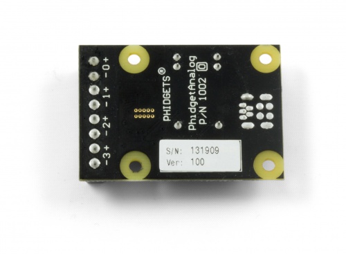
The terminal blocks on this board are labelled on the underside to save space: | |||
= | [[File:1002_0_Under.jpg|link=|500px|center]] | ||
===Isolation=== | ===Isolation=== | ||
The 1002 is not isolated. All | The 1002 is not isolated. All four channels use the same ground. | ||
===Current=== | ===Current=== | ||
The | The 1002 will limit the available current per channel at ±20mA. | ||
*For reliable results, don’t approach this limit, as it will vary from channel to channel. | |||
If your application requires a larger current source / sink, the | *For maximum accuracy, limit the current to 5mA. | ||
*If more than ±20mA of current is drawn, the device goes into a constant current supply mode. When this happens, the current will be held constant at it’s maximum value, and the output voltage will depend on the value of the load that the device is trying to drive. | |||
All the power is supplied by the USB bus. | *If your application requires a larger current source / sink, the 1002 can be used as an input to a larger external amplifier circuit. | ||
*All the power is supplied by the USB bus. | |||
===Further Reading=== | ===Further Reading=== | ||
For more information on analog outputs, see the [[Analog Output Primer]]. | For more information on analog outputs, see the [[Analog Output Primer]]. | ||
{{UGnext|}} | |||
{{ | |||
Revision as of 16:01, 17 October 2019
Getting Started
Welcome to the 1002 user guide! In order to get started, make sure you have the following hardware on hand:
- 1002 PhidgetAnalog 4-Output
- USB cable and computer
- something to use with the 1002 (multimeter, oscilloscope, device with voltage input, etc.)
Next, you will need to connect the pieces:
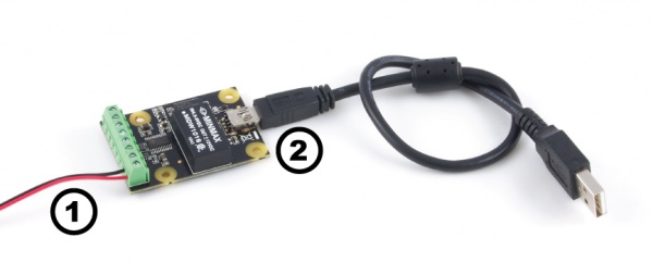
- Connect the output of the 1002 to your device. Note the polarity on the underside of the 1002.
- Connect the 1002 to your computer using the USB cable.
Now that you have everything together, let's start using the 1002!
Using the 1002
Phidget Control Panel
In order to demonstrate the functionality of the 1002, the Phidget Control Panel running on a Windows machine will be used.
The Phidget Control Panel is available for use on both macOS and Windows machines.
Windows
To open the Phidget Control Panel on Windows, find the ![]() icon in the taskbar. If it is not there, open up the start menu and search for Phidget Control Panel
icon in the taskbar. If it is not there, open up the start menu and search for Phidget Control Panel
macOS
To open the Phidget Control Panel on macOS, open Finder and navigate to the Phidget Control Panel in the Applications list. Double click on the ![]() icon to bring up the Phidget Control Panel.
icon to bring up the Phidget Control Panel.
For more information, take a look at the getting started guide for your operating system:
Linux users can follow the getting started with Linux guide and continue reading here for more information about the 1002.
First Look
After plugging the 1002 into your computer and opening the Phidget Control Panel, you will see something like this:
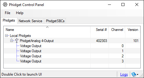
The Phidget Control Panel will list all connected Phidgets and associated objects, as well as the following information:
- Serial number: allows you to differentiate between similar Phidgets.
- Channel: allows you to differentiate between similar objects on a Phidget.
- Version number: corresponds to the firmware version your Phidget is running. If your Phidget is listed in red, your firmware is out of date. Update the firmware by double-clicking the entry.
The Phidget Control Panel can also be used to test your device. Double-clicking on an object will open an example.
Voltage Output
Double-click on the Voltage Output object in order to run the example:
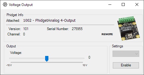
General information about the selected object will be displayed at the top of the window. You can also experiment with the following functionality:
- Set the output voltage by dragging the Voltage slider.
- Enable/disable the output voltage by toggling the Enable button.
Finding The Addressing Information
Before you can access the device in your own code, and from our examples, you'll need to take note of the addressing parameters for your Phidget. These will indicate how the Phidget is physically connected to your application. For simplicity, these parameters can be found by clicking the button at the top of the Control Panel example for that Phidget.

In the Addressing Information window, the section above the line displays information you will need to connect to your Phidget from any application. In particular, note the Channel Class field as this will be the API you will need to use with your Phidget, and the type of example you should use to get started with it. The section below the line provides information about the network the Phidget is connected on if it is attached remotely. Keep track of these parameters moving forward, as you will need them once you start running our examples or your own code.

Using Your Own Program
You are now ready to start writing your own code for the device. The best way to do that is to start from our Code Samples.
Select your programming language of choice from the drop-down list to get an example for your device. You can use the options provided to further customize the example to best suit your needs.
Once you have your example, you will need to follow the instructions on the page for your programming language to get it running. To find these instructions, select your programming language from the Programming Languages page.
Technical Details
Connections
The terminal blocks on this board are labelled on the underside to save space:
Isolation
The 1002 is not isolated. All four channels use the same ground.
Current
The 1002 will limit the available current per channel at ±20mA.
- For reliable results, don’t approach this limit, as it will vary from channel to channel.
- For maximum accuracy, limit the current to 5mA.
- If more than ±20mA of current is drawn, the device goes into a constant current supply mode. When this happens, the current will be held constant at it’s maximum value, and the output voltage will depend on the value of the load that the device is trying to drive.
- If your application requires a larger current source / sink, the 1002 can be used as an input to a larger external amplifier circuit.
- All the power is supplied by the USB bus.
Further Reading
For more information on analog outputs, see the Analog Output Primer.
What to do Next
- Programming Languages - Find your preferred programming language here and learn how to write your own code with Phidgets!
- Phidget Programming Basics - Once you have set up Phidgets to work with your programming environment, we recommend you read our page on to learn the fundamentals of programming with Phidgets.