Products for USB Sensing and Control


Solid State Relays, or SSRs, are devices designed to operate like standard relays but without mechanical motion.
The SSR Board is safe to use with sensitive control devices like microprocessors, and will not damage a Phidget device or your PC. The board is isolated from input to output and protected against static discharge and surges from inductive loads.
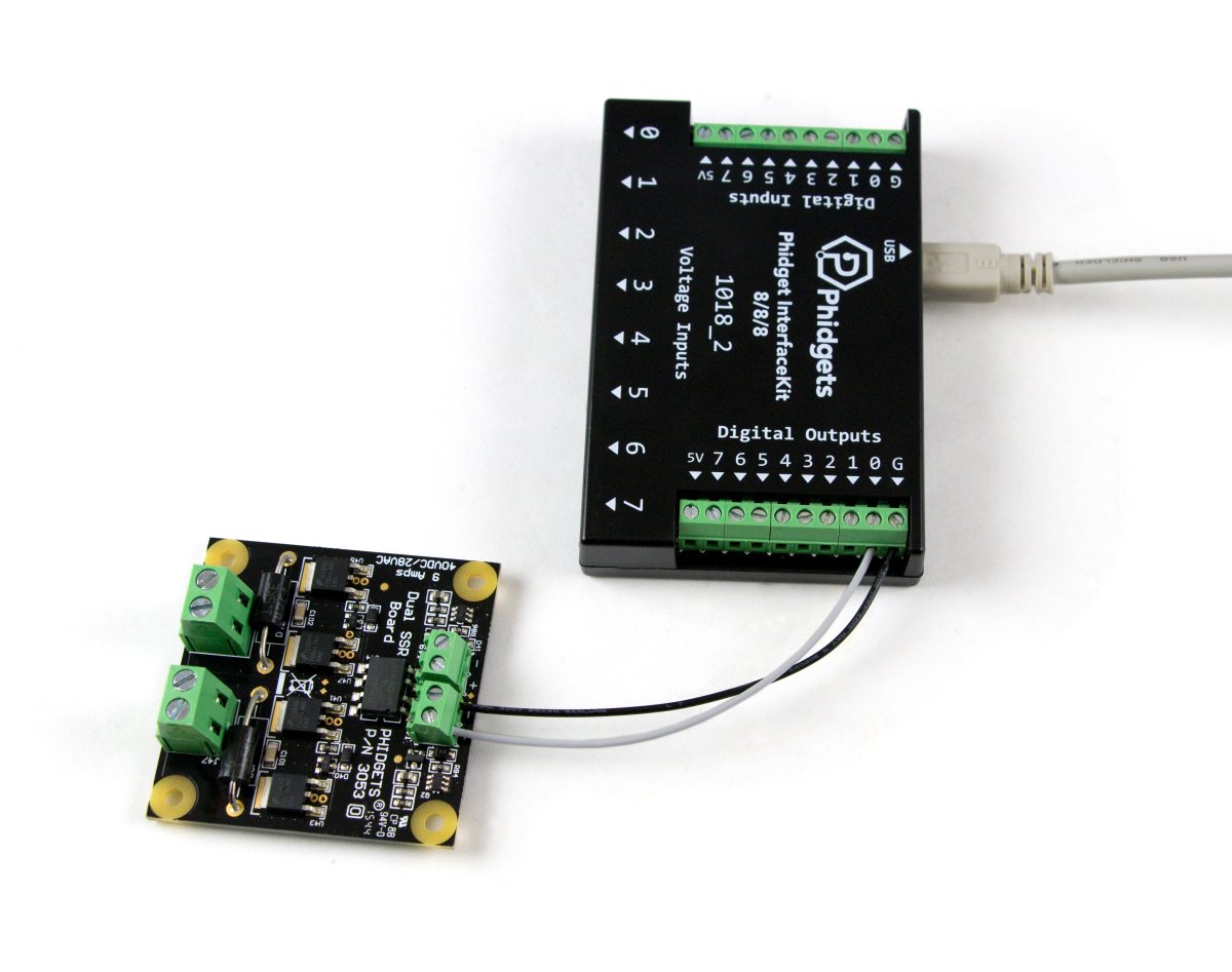
This SSR board can be controlled with 5V digital outputs. For more details, see the Connection & Compatibility tab.
This relay board is controlled by 5V digital outputs. Just connect the '+' terminal to the digital output and the '-' terminal to the ground on your device using a bit of wire.
| Product | Digital Outputs | Board Properties | |||
|---|---|---|---|---|---|
| Part Number | Price | Number of Digital Outputs | Digital Output Current Max | Digital Output Voltage Max | Controlled By |
 PhidgetInterfaceKit 8/8/8 Mini-Format
|
$70.00 | 8 | 16 mA | 5 V DC | USB (Mini-USB) |
 PhidgetInterfaceKit 2/2/2
|
$50.00 | 2 | 16 mA | 5 V DC | USB (Mini-USB) |
 PhidgetInterfaceKit 8/8/8
|
$80.00 | 8 | 16 mA | 5 V DC | USB (Mini-USB) |
 PhidgetInterfaceKit 8/8/8
|
$80.00 | 8 | — | 5 V DC | USB (Mini-USB) |
 PhidgetInterfaceKit 8/8/8 w/6 Port Hub
|
$110.00 | 8 | 16 mA | 5 V DC | USB (Mini-USB) |
 PhidgetTextLCD 20X2 : White : Integrated PhidgetInterfaceKit 8/8/8
|
$70.00 | 8 | 16 mA | 5 V DC | USB (Mini-USB) |
 4x Digital Output Phidget
|
$15.00 | 4 | 16 mA | 5 V DC | VINT |
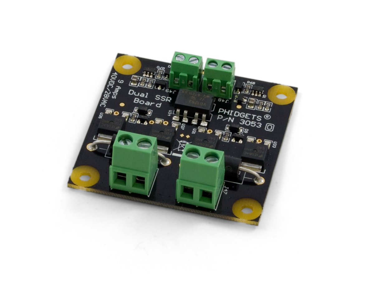
You can protect your board from dust and debris by purchasing an enclosure. An enclosure will also prevent unintentional shorts caused by objects touching the pins on the bottom of the board or any terminal screws.
| Product | Physical Properties | |
|---|---|---|
| Part Number | Price | Material |
 Acrylic Enclosure for the 3053
|
$8.00 | Clear Acrylic |
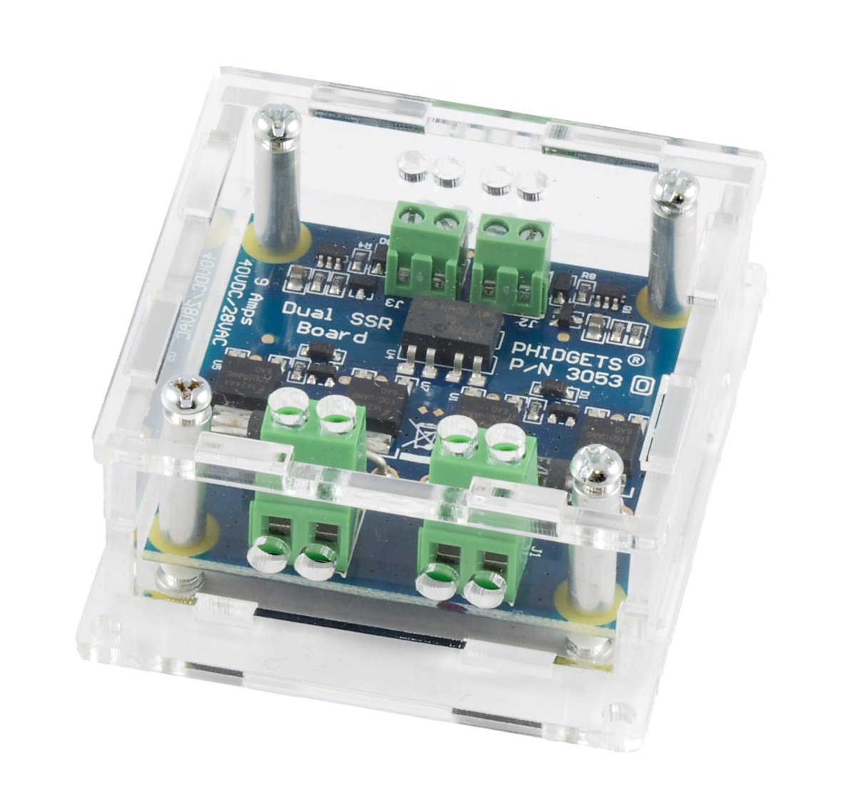
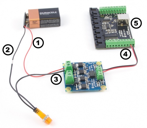
Welcome to the 3053 user guide! In order to get started, make sure you have the following hardware on hand:
Next, you will need to connect the pieces:
Now that you have everything together, let's start using the 3053!
In order to demonstrate the functionality of the 3053, we will connect it to the 1018, and then run an example using the Phidget Control Panel on a Windows machine.
The Phidget Control Panel is available for use on both macOS and Windows machines. If you would like to follow along, first take a look at the getting started guide for your operating system:
Linux users can follow the getting started with Linux guide and continue reading here for more information about the 3053.
After plugging in the 3053 into the 1018, and the 1018 into your computer, open the Phidget Control Panel. You will see something like this:
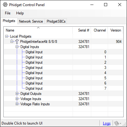
The Phidget Control Panel will list all connected Phidgets and associated objects, as well as the following information:
The Phidget Control Panel can also be used to test your device. Double-clicking on an object will open an example.
Double-click on a Digital Output object in order to run the example:
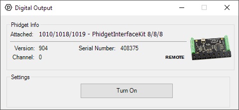
General information about the selected object will be displayed at the top of the window. You can also experiment with the following functionality:
Solid State Relays, or SSRs, are devices designed to operate like standard relays but without mechanical motion. Built instead out of silicon transistors, SSRs allow currents and voltages to be switched by simple digital signals from a microprocessor or any other device that can supply the small amount of current needed to activate the SSR’s internal switching mechanism. For more information on solid state relays, refer to the SSR Guide.
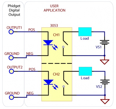
Using the SSR Relay Board in your application is typically done according to the diagram on the right, though there are other implementations for it as well. The SSR control inputs can be controlled with a wide range of voltage levels between 3 and 30V. Be sure to match the polarity of the control signal with the ± labels on the input terminal blocks. One concern with any type of relay is the turn-on and turn-off times. Since the SSR Board uses optoisolation, the turn-on delay depends on how strong the control signal is, while the turn-off delay is quite constant, and quick. The 3053 uses internal circuitry to keep the current of the control signal around 10mA, no matter how what voltage level is used. To improve the turn-on time of the SSR, a short current spike (approximately 35mA for 300μs) at turn-on is possible if your control signal can provide it. This allows the SSR to turn on quicker, reducing heating during the turn-on transition. If your control signal is not able to provide the 35mA, the SSR will turn on anyway, but will take up to 50% longer.
The SSR Board is safe to use with sensitive control devices like microprocessors, and will not damage a Phidget or your PC. This is achieved through the use of an optoisolation chip - creating a physical barrier between the SSR control inputs and the potentially high voltage and high current outputs. In addition to the optoisolation between the inputs and outputs, there is an on-board 47V voltage supression device across the relay output that protects the board from static electricity and surges from inductive loads. To protect the optoisolation LEDs from potential overcurrent on the inputs, a transistor-based current limiting circuit has been added. The circuit limits the constant current travelling through the LEDs to 10mA, regardless of the input voltage. The transistors dissipate what would have been extra current in the form of heat. The 3053 Dual SSR Board comprises of two channels. Both channels are electrically and physically isolated from each other, and are controlled individually.
The SSR Board is able to safely switch at a speed of 20Hz. This board is not intended as a high frequency switch due to the extreme heating that will occur. Although it is possible to switch the SSR Board at up to 300Hz, it easily produces enough heat to liquefy the solder underneath the transistors (which requires at least 240°C) at a 3A load.
This device doesn't have an API of its own. It is controlled by opening two DigitalOutputs channels on the Phidget that it's connected to. For a list of compatible Phidgets with Digital Outputs, see the Connection & Compatibility tab.
You can find details for the DigitalOutput API on the API tab for the Phidget that this relay connects to.
| Electrical Properties | |
|---|---|
| Relay Output Type | MOSFET |
| Isolation Method | Photoelectric |
| Dielectric Strength | 5.3 kV AC |
| Control Voltage Min | 3 V DC |
| Control Voltage Max | 30 V DC |
| Control Current | 10 mA |
| Load Voltage Max (DC) | 40 V DC |
| Load Voltage Max (AC) | 28 V AC |
| Load Current Max (AC) | (per channel) 9 A |
| Load Current Max (DC) | (per channel) 9 A |
| Turn-on Time Max | 1.9 ms |
| Turn-off Time Max | 0.16 ms |
| Contact Resistance Max | 50 mΩ |
| Switching Speed Max | 300 cps |
| Physical Properties | |
| Recommended Wire Size (Control) | 16 - 26 AWG |
| Recommended Wire Size (Load) | 12 - 24 AWG |
| Operating Temperature Min | -40 °C |
| Operating Temperature Max | 100 °C |
| Customs Information | |
| Canadian HS Export Code | 8473.30.00 |
| American HTS Import Code | 8473.30.51.00 |
| Country of Origin | CN (China) |
| Date | Board Revision | Device Version | Comment |
|---|---|---|---|
| May 2010 | 0 | N/A | Product Release |
| Product | Electrical Properties | ||||
|---|---|---|---|---|---|
| Part Number | Price | Load Current Max (AC) | Load Voltage Max (AC) | Load Current Max (DC) | Load Voltage Max (DC) |
 PhidgetInterfaceKit 0/16/16
|
$95.00 | — | — | — | — |
 PhidgetInterfaceKit 0/0/4
|
$55.00 | 12 A | 277 V AC | 7 A | * 30 V DC |
 PhidgetInterfaceKit 0/0/4
|
$55.00 | 12 A | 277 V AC | 7 A | * 30 V DC |
 PhidgetInterfaceKit 0/0/8
|
$85.00 | 2 A | 250 V AC | 2 A | * 120 V DC |
 PhidgetInterfaceKit 0/0/8
|
$85.00 | 2 A | 250 V AC | 2 A | 120 V DC |
 Dual Relay Board
|
$17.00 | 12 A | 277 V AC | 7 A | * 30 V DC |
 SSR Relay Board 2.5A
|
$15.00 | 2.5 A | 28 V AC | 2.5 A | 40 V DC |
 Dual SSR Relay Board
|
$30.00 | (per channel) 9 A | 28 V AC | (per channel) 9 A | 40 V DC |
 SSR Relay Board 0.5A
|
$10.00 | 500 mA | 28 V AC | 500 mA | 40 V DC |
 4x Relay Phidget
|
$30.00 | 12 A | 277 V AC | 7 A | * 30 V DC |
 4x Isolated Solid State Relay Phidget
|
$25.00 | — | — | (per channel) 8 A | (per channel) 30 V DC |
 16x Isolated Solid State Relay Phidget
|
$50.00 | — | — | (per channel) 8 A | (per channel) 30 V DC |
 Relay Phidget
|
$10.00 | 12 A | 277 V AC | 7 A | * 30 V DC |
 Signal Relay Phidget
|
$12.00 | 2 A | 240 V AC | 2 A | 120 V DC |
 Solid State Relay Phidget
|
$15.00 | 10 A | 30 V AC | * 10 A | 30 V DC |