Mechanical Relay Guide
Mechanical relays can switch a power or signal line by physically moving metal contacts with an electromagnet. Learn more here.
Replaced by the 3051 - Dual Relay Board.
The Dual Relay Board allows digital outputs of the 1018 InterfaceKit 8/8/8, the 1202 Text LCD or the 1203 TextLCD to control larger loads and devices like AC or DC motors, electromagnets, solenoids, and incandescent light bulbs.
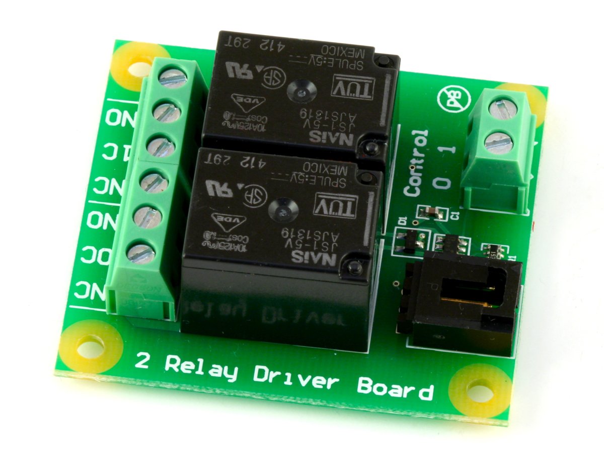
The 3051 contains 2 relays for switching AC or DC power.
The relays are Single Pole Double Throw (SPDT)
The Solid State Relay can switch up to 240 V AC at 10 Amps and 100 V DC at 5 Amps.
| Date | Board Revision | Device Version | Comment |
|---|---|---|---|
| October 2007 | 0 | N/A | Product Release |
| September 2008 | 1 | N/A | Bigger connectors, Bigger board |
Welcome to the 3051 user guide! In order to get started, make sure you have the following hardware on hand:
Next, you will need to connect the pieces:
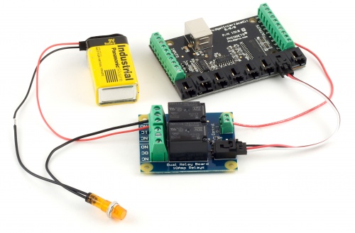
Now that you have everything together, let's start using the 3051!
In order to demonstrate the functionality of the 3051, we will connect it to the 1018, and then run an example using the Phidget Control Panel on a Windows machine.
The Phidget Control Panel is available for use on both macOS and Windows machines. If you would like to follow along, first take a look at the getting started guide for your operating system:
Linux users can follow the getting started with Linux guide and continue reading here for more information about the 3051.
After plugging in the 3051 into the 1018, and the 1018 into your computer, open the Phidget Control Panel. You will see something like this:
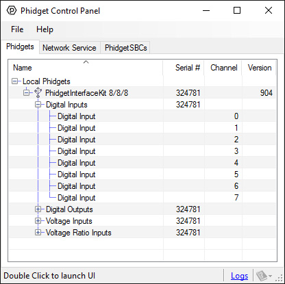
The Phidget Control Panel will list all connected Phidgets and associated objects, as well as the following information:
The Phidget Control Panel can also be used to test your device. Double-clicking on an object will open an example.
Double-click on a Digital Output object in order to run the example:
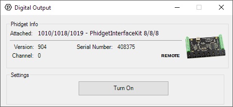
General information about the selected object will be displayed at the top of the window. You can also experiment with the following functionality:
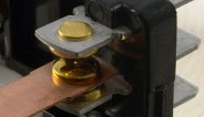
A relay is an electrically-controlled switch. Although many types of electrical switches exist, a relay's mechanical nature gives it the advantage of reliability and current-switching capacity. The main disadvantage to using mechanical relays is their limited life-span, as opposed to solid state relays who do not suffer from this drawback. For more information on mechanical relays refer to the Mechanical Relay Guide
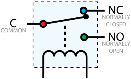
Relays have a connection scheme determined by the arrangement of contacts within the relay. Because relays are a type of switch, they are defined in the same way other electromechanical switches are defined. In switch schemes, the number of poles represents the number of common terminals a switch has, and the number of throws represents the number of switchable terminals that exist for each pole. The relays used in the Dual Relay Board are SPDT relays: single pole, double throw. The internal construction of this type of relay is depicted in the diagram to the right. Many other types of relays exist: SPST, DPDT, and DPST, to name a few. In an SPDT relay, one of the throw terminals is labelled Normally Closed (NC), and the other is labelled Normally Open (NO). As the name indicates, the normally closed terminal is the terminal connected to common when the relay coil is not powered. When the relay coil is energized by the relay control circuit, the electromagnetic field of the coil forces the switch element inside the relay to break its contact with the normally closed terminal and make contact with the normally open terminal. The switch element would then connect the normally open terminal and the common terminal.
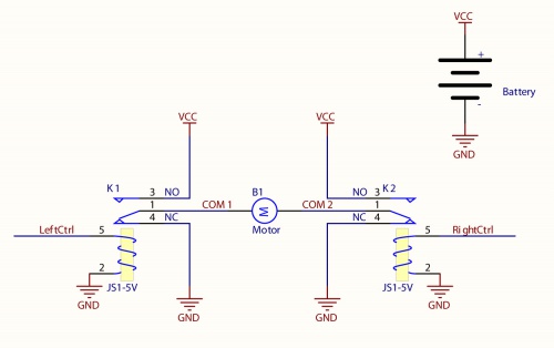
Connect the load to the COM terminals, in this case the wires of a DC motor. The Normally Open (NO) terminals are connected to the power supply (VCC), and the Normally Closed (NC) terminals are connected to the ground (GND) of the power supply. Connect the Control pins to a digital output. You can toggle the corresponding output to switch the relays. Looking at the diagram, when LeftCtrl is enabled and RightCtrl is disabled, the current will flow from the NO terminal of relay K1 through the motor and into the NC terminal of relay K2. This will cause the motor to rotate in one direction. Similarily, if LeftCtrl is disabled and RightCtrl is enabled, the current will flow from the NO terminal of relay K2 through the motor and into the NC terminal of relay K1. This will cause the motor to rotate in the opposite direction. When both LeftCtrl and RightCtrl are disabled, both ends of the motor will be shorted to ground and no current will flow. When both leftCtrl and RightCtrl are enabled, both ends of the motor will be shorted to VCC and again, no current will flow.
When a relay is in one switch position for a period of time, oxidation of the open contact(s) can occur. Depending upon the internal coating material of the contacts, oxide films of varying density will be displaced upon the surface of open contacts; this film acts as an insulator to current flow. When the relay is switched, a certain amount of current flowing through the contacts, known as the wetting current, is required to remove the film of oxides and ensure proper conduction. Because of this requirement, these relays are not reliable for signal switching. See the device specification on page 10 for detailed requirements.
If highly inductive loads are used with the Dual Relay Board, it is recommended that a noise limiting component be used to prevent damage to the device. An MOV, TVS diode, or kickback diode (for DC applications) shunted across the load will assist in dissipating voltage transients.
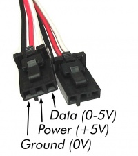
The Phidget Cable is a 3-pin, 0.100 inch pitch locking connector. Pictured here is a plug with the connections labelled. The connectors are commonly available - refer to the Analog Input Primer for manufacturer part numbers.